
1.4: Advanced Biotechnology Equipment
- Page ID
- 157028
\( \newcommand{\vecs}[1]{\overset { \scriptstyle \rightharpoonup} {\mathbf{#1}} } \)
\( \newcommand{\vecd}[1]{\overset{-\!-\!\rightharpoonup}{\vphantom{a}\smash {#1}}} \)
\( \newcommand{\dsum}{\displaystyle\sum\limits} \)
\( \newcommand{\dint}{\displaystyle\int\limits} \)
\( \newcommand{\dlim}{\displaystyle\lim\limits} \)
\( \newcommand{\id}{\mathrm{id}}\) \( \newcommand{\Span}{\mathrm{span}}\)
( \newcommand{\kernel}{\mathrm{null}\,}\) \( \newcommand{\range}{\mathrm{range}\,}\)
\( \newcommand{\RealPart}{\mathrm{Re}}\) \( \newcommand{\ImaginaryPart}{\mathrm{Im}}\)
\( \newcommand{\Argument}{\mathrm{Arg}}\) \( \newcommand{\norm}[1]{\| #1 \|}\)
\( \newcommand{\inner}[2]{\langle #1, #2 \rangle}\)
\( \newcommand{\Span}{\mathrm{span}}\)
\( \newcommand{\id}{\mathrm{id}}\)
\( \newcommand{\Span}{\mathrm{span}}\)
\( \newcommand{\kernel}{\mathrm{null}\,}\)
\( \newcommand{\range}{\mathrm{range}\,}\)
\( \newcommand{\RealPart}{\mathrm{Re}}\)
\( \newcommand{\ImaginaryPart}{\mathrm{Im}}\)
\( \newcommand{\Argument}{\mathrm{Arg}}\)
\( \newcommand{\norm}[1]{\| #1 \|}\)
\( \newcommand{\inner}[2]{\langle #1, #2 \rangle}\)
\( \newcommand{\Span}{\mathrm{span}}\) \( \newcommand{\AA}{\unicode[.8,0]{x212B}}\)
\( \newcommand{\vectorA}[1]{\vec{#1}} % arrow\)
\( \newcommand{\vectorAt}[1]{\vec{\text{#1}}} % arrow\)
\( \newcommand{\vectorB}[1]{\overset { \scriptstyle \rightharpoonup} {\mathbf{#1}} } \)
\( \newcommand{\vectorC}[1]{\textbf{#1}} \)
\( \newcommand{\vectorD}[1]{\overrightarrow{#1}} \)
\( \newcommand{\vectorDt}[1]{\overrightarrow{\text{#1}}} \)
\( \newcommand{\vectE}[1]{\overset{-\!-\!\rightharpoonup}{\vphantom{a}\smash{\mathbf {#1}}}} \)
\( \newcommand{\vecs}[1]{\overset { \scriptstyle \rightharpoonup} {\mathbf{#1}} } \)
\(\newcommand{\longvect}{\overrightarrow}\)
\( \newcommand{\vecd}[1]{\overset{-\!-\!\rightharpoonup}{\vphantom{a}\smash {#1}}} \)
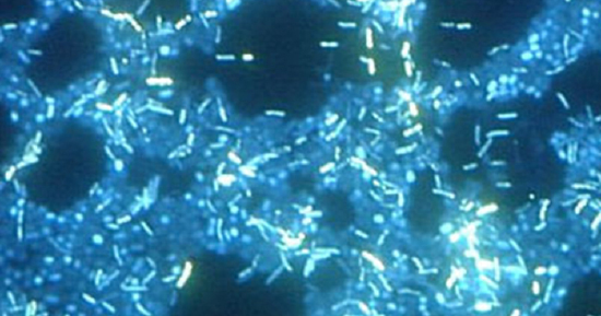
\(\newcommand{\avec}{\mathbf a}\) \(\newcommand{\bvec}{\mathbf b}\) \(\newcommand{\cvec}{\mathbf c}\) \(\newcommand{\dvec}{\mathbf d}\) \(\newcommand{\dtil}{\widetilde{\mathbf d}}\) \(\newcommand{\evec}{\mathbf e}\) \(\newcommand{\fvec}{\mathbf f}\) \(\newcommand{\nvec}{\mathbf n}\) \(\newcommand{\pvec}{\mathbf p}\) \(\newcommand{\qvec}{\mathbf q}\) \(\newcommand{\svec}{\mathbf s}\) \(\newcommand{\tvec}{\mathbf t}\) \(\newcommand{\uvec}{\mathbf u}\) \(\newcommand{\vvec}{\mathbf v}\) \(\newcommand{\wvec}{\mathbf w}\) \(\newcommand{\xvec}{\mathbf x}\) \(\newcommand{\yvec}{\mathbf y}\) \(\newcommand{\zvec}{\mathbf z}\) \(\newcommand{\rvec}{\mathbf r}\) \(\newcommand{\mvec}{\mathbf m}\) \(\newcommand{\zerovec}{\mathbf 0}\) \(\newcommand{\onevec}{\mathbf 1}\) \(\newcommand{\real}{\mathbb R}\) \(\newcommand{\twovec}[2]{\left[\begin{array}{r}#1 \\ #2 \end{array}\right]}\) \(\newcommand{\ctwovec}[2]{\left[\begin{array}{c}#1 \\ #2 \end{array}\right]}\) \(\newcommand{\threevec}[3]{\left[\begin{array}{r}#1 \\ #2 \\ #3 \end{array}\right]}\) \(\newcommand{\cthreevec}[3]{\left[\begin{array}{c}#1 \\ #2 \\ #3 \end{array}\right]}\) \(\newcommand{\fourvec}[4]{\left[\begin{array}{r}#1 \\ #2 \\ #3 \\ #4 \end{array}\right]}\) \(\newcommand{\cfourvec}[4]{\left[\begin{array}{c}#1 \\ #2 \\ #3 \\ #4 \end{array}\right]}\) \(\newcommand{\fivevec}[5]{\left[\begin{array}{r}#1 \\ #2 \\ #3 \\ #4 \\ #5 \\ \end{array}\right]}\) \(\newcommand{\cfivevec}[5]{\left[\begin{array}{c}#1 \\ #2 \\ #3 \\ #4 \\ #5 \\ \end{array}\right]}\) \(\newcommand{\mattwo}[4]{\left[\begin{array}{rr}#1 \amp #2 \\ #3 \amp #4 \\ \end{array}\right]}\) \(\newcommand{\laspan}[1]{\text{Span}\{#1\}}\) \(\newcommand{\bcal}{\cal B}\) \(\newcommand{\ccal}{\cal C}\) \(\newcommand{\scal}{\cal S}\) \(\newcommand{\wcal}{\cal W}\) \(\newcommand{\ecal}{\cal E}\) \(\newcommand{\coords}[2]{\left\{#1\right\}_{#2}}\) \(\newcommand{\gray}[1]{\color{gray}{#1}}\) \(\newcommand{\lgray}[1]{\color{lightgray}{#1}}\) \(\newcommand{\rank}{\operatorname{rank}}\) \(\newcommand{\row}{\text{Row}}\) \(\newcommand{\col}{\text{Col}}\) \(\renewcommand{\row}{\text{Row}}\) \(\newcommand{\nul}{\text{Nul}}\) \(\newcommand{\var}{\text{Var}}\) \(\newcommand{\corr}{\text{corr}}\) \(\newcommand{\len}[1]{\left|#1\right|}\) \(\newcommand{\bbar}{\overline{\bvec}}\) \(\newcommand{\bhat}{\widehat{\bvec}}\) \(\newcommand{\bperp}{\bvec^\perp}\) \(\newcommand{\xhat}{\widehat{\xvec}}\) \(\newcommand{\vhat}{\widehat{\vvec}}\) \(\newcommand{\uhat}{\widehat{\uvec}}\) \(\newcommand{\what}{\widehat{\wvec}}\) \(\newcommand{\Sighat}{\widehat{\Sigma}}\) \(\newcommand{\lt}{<}\) \(\newcommand{\gt}{>}\) \(\newcommand{\amp}{&}\) \(\definecolor{fillinmathshade}{gray}{0.9}\)A biofilm is a complex community of one or more microorganism species, typically forming as a slimy coating attached to a surface. In nature, biofilms are abundant and frequently occupy complex niches within ecosystems (Figure \(\PageIndex{1}\)). In medicine, biofilms can coat medical devices and exist within the body. Because they possess unique characteristics, such as increased resistance against the immune system and to antimicrobial drugs, biofilms are of particular interest to microbiologists and clinicians alike. Because biofilms are thick, they cannot be observed very well using conventional light microscopy or electron microscopy. This is because slicing a biofilm to create a thinner specimen might kill or disturb the microbial community. Confocal microscopy, in combination with fluorescent dyes or antibodies, is often used to image biofilms because it scans the film on one z-plane at a time and produces a three-dimensional image of a thick specimen.

Introduction
The biotech laboratory often requires specialized equipment to conduct experiments and analyze results. This equipment can include several types of microscopes, PCR machines for DNA amplification, and DNA sequencers.
By the end of this page, you will be able to:
- Identify and describe the parts of a brightfield microscope
- Calculate total magnification for a compound microscope
- Describe the distinguishing features and typical uses for various types of light microscopes and electron microscopes
- Describe the thermocycler or PCR machine
- Describe how flow cytometers can analyze cells
The Microscope
A microscope is an instrument used to magnify an object. The technique of using a microscope is called microscopy. Through their work, the early pioneers of microscopy, including Zacharias Janssen (1590s) and Anton von Leeuwenhoek (1670s), opened a window into the invisible world of microorganisms. These microscopes were rudimentary, using a light source and simple glass magnifying lenses. However, microscopy continued to advance in the centuries that followed. In 1830, Joseph Jackson Lister essentially created the first modern compound light microscope, a microscope that combines multiple lenses for magnification, together with a lamp for visible light. The 20th century saw the development of more advanced microscopes, such as the fluorescent microscope, which uses an ultraviolet light source, and the electron microscope, which uses short-wavelength electron beams. These advances led to major improvements in magnification, resolution, and contrast.
The two major categories of microscopes are light microscopes and electron microscopes. However, advancements in microscopy has created a third category, the atomic microscope (i.e., scanning probe microscope) which uses physical probes to examine objects at the atomic level.
While differences exist between the types of microscopes, most microscopes have the same basic components. These components are best exemplified in the compound light microscope shown in Figure \(\PageIndex{2}\).
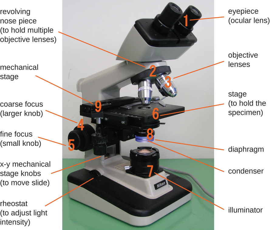
The components of a compound light microscope include the:
- mechanical stage: the platform of the microscope where the specimen is placed and secured
- x-y mechanical stage knobs: for movement of the stage in the x-y plane
- eyepiece: used to view the specimen; in light microscopes it contains an ocular lens
- ocular lens: found in the eyepiece of light microscopes; typically magnify images 10x to 15x
- objective lens: provide different levels of magnification (i.e. "power"); made of glass in light microscopy; in electron microscopy, the objective lenses are electromagnetic
- objective lens nosepiece: a rotating nosepiece containing all objective lenses
- coarse focus knob: used for large-scale movements of the stage up and down in order to focus on the specimen
- fine focus knob: used for small-scale movements of the stage up and down in order to focus on the specimen; used for low power objective lenses (e.g. 4X and 10X)
- illuminator: provides an energy source in the form of visible light, ultra-violet light, or electrons for viewing the specimen
- condenser: focuses the illuminator on specimen to improve image clarity; the position can be optimized
- rheostat: a dimmer switch that controls the intensity of the illuminator
- diaphragm (i.e., iris): controls the amount of energy (e.g. light) passing through the condenser
In microscopy, magnification is how much larger the object appears compared to the size of the actual specimen. In electron microscopy, magnification is determined by the interaction between the electron beam, the electromagnetic objective lenses and the image projection system. In light microscopy, magnification is provided by both the objective lens and the ocular lens.
The total magnification is the product of the ocular magnification and objective magnification and is calculated using this formula:
\[\text{total magnification}=\text{ocular magnification} \times \text{objective magnification} \nonumber\]
For example, if a 40X objective lens is selected and the ocular lens is 10X, the total magnification would be:
\[(40×)(10×)=400× \nonumber\]
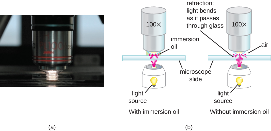
Contrast is the difference in light intensity between an object and its background, allowing for better detail when observing the object. Contrast can be enhanced in microscopy though the use of stains or the use of microscope filters. Resolution is the ability to distinguish two objects as separate entities. The higher the resolution, the clearer the image. In light microscopy, resolution may be compromised at very high magnification. When light passes through the small amount of air between the specimen and the lens, the differences in their refractive indices scatters the light rays before they can be focused by the objective lens. To solve this problem, a drop of immersion oil can be used to fill the space between the specimen and the objective lens. Since immersion oil has a refractive index very similar to that of glass, it decreases light scattering and increases the amount of light collected by the objective lens (Figure \(\PageIndex{3}\)). A variety of oils can be used for different types of light. However, only one type of objective lens can be used. This lens, known as an oil immersion lens, is a special lens designed to be used with immersion oils.
Light microscopy
The concept of light microscopy is relatively straightforward. The specimen is processed and secured to the stage. The illuminator is turned on and the condenser focuses the light onto the specimen. The intensity of the light from the illuminator can be adjusted using the diaphragm. The specimen must be thin enough for the light to pass through. Staining techniques may be used to enhance the contrast of the specimen. The light passes through the specimen and is collected by the objective lens. Modern objectives are actually several glass lenses stacked on top of one another that act to collect the light passing through the specimen and focus it up towards the body of the microscope towards the ocular lens. The ocular lens will have an additional glass lens that magnifies the image further. Most light microscopes will have several objective lenses of increasing power (4X, 10X, 20X, 40X, 100X) on a rotating nosepiece. The revolving nosepiece of the microscope allows for objective lenses of different magnification or "power" to be chosen. As the power of the objective lens is increased, the amount of light passing through it decreases. This will require increased illumination, which is controlled by the rheostat. The coarse focus knob is adjusted to bring the specimen into rough focus, while the fine focus knob can fine tune the focus for finer details. e;
Some of the major types of light microscopes are:
- Brightfield microscope
- Darkfield microscope
- Phase-contrast microscope
- Fluorescence microscope
- Confocal Laser Scanning microscope
- Polarizing microscope
Today, a biotech lab might use several types of light microscopes to advance the progress of their research.
The Brightfield Microscope
The brightfield microscope is perhaps the most common type of light microscope used in a biotech lab. The brightfield microscope (often just called a light microscope) is a compound light microscope that uses its lenses to produce a dark image on a bright background. Older brightfield microscopes are monocular (having a single eyepiece), while most newer brightfield microscopes are binocular (having two eyepieces). As described above, the condenser of the brightfield microscope directs light from the illuminator up through the specimen into the objective lens and then the ocular lens to produce a magnified image. Structures in the specimen will appear darker, to various extents, than the bright background, creating maximally sharp images at total magnifications up to about 1000x. Further magnification using a brightfield microscope would create a larger image, but with poor resolution.
The Darkfield Microscope
The darkfield microscope is a brightfield microscope that has a small but significant modification to the condenser. A small, opaque disk, called an light stop or illumination block, is placed between the light source and the condenser lens. As light passes through the condenser on its way to the objective lens, most of it is blocked by the light block. This produces a hollow cone of light that passes through the specimen. The only light that reaches the objective lens is light that has been refracted or reflected by structures in the specimen. The resulting image typically shows bright objects on a dark background (Figure \(\PageIndex{4}\)).
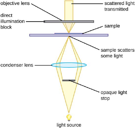
Darkfield microscopy can often create high-contrast, high-resolution images of specimens without the use of fixatives and stains, which is particularly useful for viewing live specimens that might be killed or otherwise compromised by the stains.
The Phase-Contrast Microscope
The phase-contrast microscope is actually the oldest and simplest type of light microscope. The phase-contrast microscope creates a high-contrast, high-resolution image by altering the wavelengths of light rays passing through the specimen. To create these altered wavelength paths, an annular stop is used in the condenser. The annular stop produces a hollow cone of light that is is focused on the specimen. Some of this light will enter the objective lens having passed through the specimen unchanged (ie. undiffracted), whereas some of the light will be slowed and shifted by dense structures in the specimen (i.e. diffracted). The difference between undiffracted and diffracted light within the objective lens is known as a phase shift. The objective lens contains a phase plate, with a phase ring. As the diffracted light enters the phase plate, its phase shift is increased in comparison to the undiffracted light (Figure \(\PageIndex{5}\)). Areas of high phase shift are seen as dark regions in the specimen, with the undiffracted light showing as brighter areas.


Because it increases contrast without requiring stains, phase-contrast microscopy is often used to observe live specimens. Certain structures, such as organelles in eukaryotic cells and endospores in prokaryotic cells, are especially well visualized with phase-contrast microscopy (Figure \(\PageIndex{7}\)) .
The Fluorescence Microscope
A fluorescent microscope is a type of light microscope that uses fluorescent dyes or proteins to visualize specific structures. These fluorescence dyes or proteins are known as fluorochromes, which are capable of absorbing energy from a light source and then emitting this energy as visible light. Fluorochromes include naturally fluorescent substances (such as chlorophyll), as well as fluorescent stains that are added to the specimen to create contrast. Dyes such as Texas Red and Fluorescein Isothiocyanate (FITC) are examples of fluorochromes. Other examples include the nucleic acid dyes 4’,6’-diamidino-2-phenylindole (DAPI) and acridine orange. Fluorescence microscopes can be used to identify pathogens, to find a particular species within an environment, or to find the locations of particular molecules and structures within a cell. Approaches have also been developed to distinguish living from dead cells using fluorescence microscopy based upon whether they take up particular fluorochromes. Sometimes, multiple fluorochromes are used on the same specimen to show different structures or features.
In fluorescence microscopy, the microscope transmits light of short wavelength excitation, such as ultraviolet or blue light, towards the specimen; the fluorochromes absorb this excitation light and emit visible light with longer wavelengths. This emission light is directed towards the ocular lenses using a dichrotic mirror located below the ocular. The emitted light is filtered (in part because ultraviolet light is harmful to the eyes) so that only visible light (in the form of fluorescence) reaches the ocular lens (Figure \(\PageIndex{6}\)). This produces an image of the specimen in bright colors against a dark background.

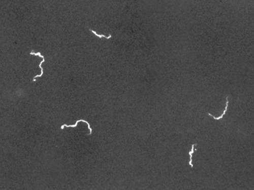
One of the most important applications of fluorescence microscopy is a technique called immunofluorescence, which is used to identify certain structures or organisms using fluorescently-labeled antibodies. There are two approaches to this technique: direct immunofluorescence and indirect immunofluorescence (Figure \(\PageIndex{7}\)) . In direct immunofluorescence, antibodies known as primary antibodies are coupled to a fluorochrome. The binding of this labeled primary antibody to its target antigen (usually a protein) permits visualization of the structure expressing this antigen. In indirect immunofluorescence, antibodies known as secondary antibodies are coupled to the fluorochrome, rather than primary antibodies. The unlabeled primary antibody binds to its antigen, followed by binding of the labeled secondary antibody to the primary antibody. Since multiple secondary antibodies can often attach to a single primary antibody, IFA amplifies the fluorescence being emitted, making it easier visualize features in a specimen.

b) Indirect immunofluorescence is used to visualize larvae of Schistosoma mansoni, a parasitic worm that causes schistosomiasis, an intestinal disease common in the tropics. (c) In direct immunofluorescence, a fluorochrome is coupled to the primary antibody, which binds to the antigen. In indirect immunofluorescence, the fluorochrome is coupled to the secondary antibody, which binds to a primary antibody, which, in turn, binds to the antigen. (images from OpenStax Microbiology, CC BY-SA 4.0)
Animation: Fluorescence Microscopy
The Confocal Microscope
A confocal microscope is a specialized fluorescent microscope that uses a laser to excite the fluorochromes and a pinhole aperture to remove out of focus fluorescence and enhance image clarity. Whereas a conventional fluorescent microscope creates an image by focusing on the image at a single depth (or z-plane), a confocal microscope uses a laser to scan multiple z-planes within the object. This produces numerous two-dimensional, high-resolution images at various depths, which can be constructed into a three-dimensional image by a computer (Figure \(\PageIndex{8}\)). Because of this, confocal microscopy is also known as confocal laser scanning microscopy.

Electron Microscopy
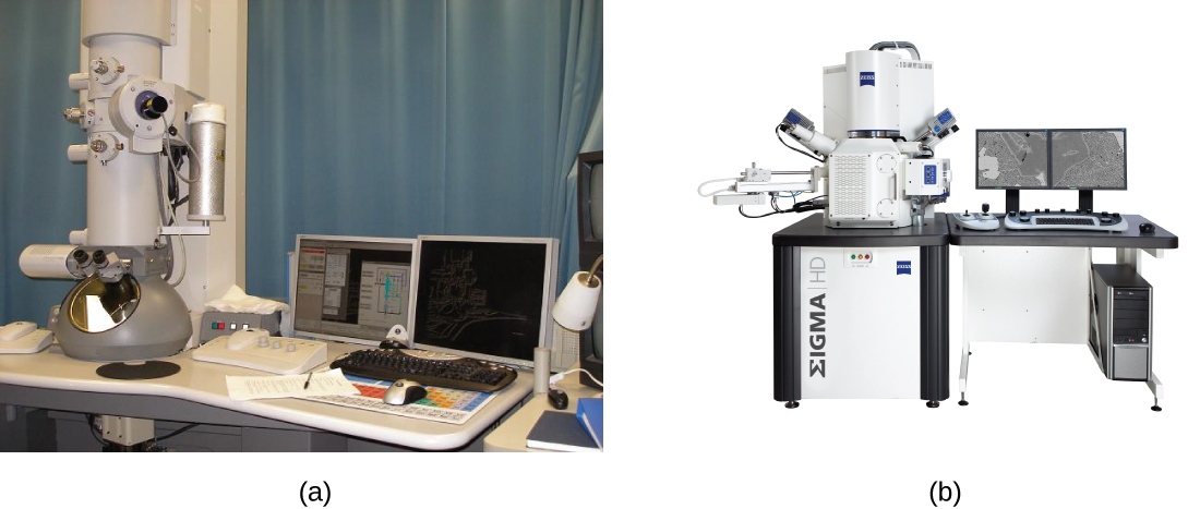
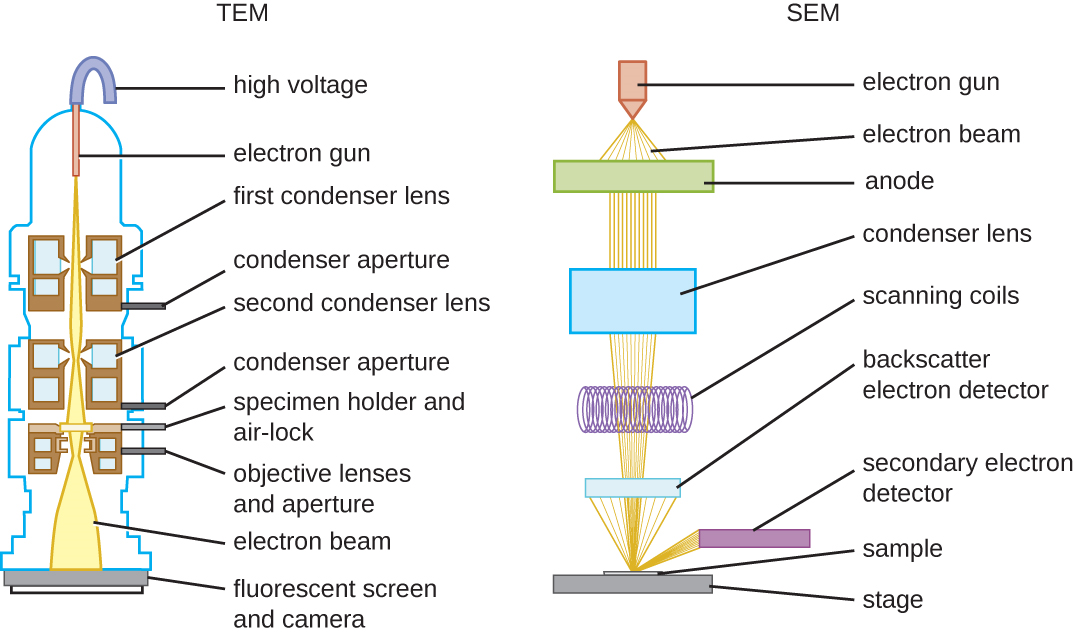
The maximum theoretical resolution of images created by light microscopes is limited by the longer wavelengths of visible light. Most light microscopes can only magnify 1000X, and a few can magnify up to 1500X, but this does not begin to approach the magnifying power of an electron microscope (EM). The EM is an imaging tool that uses short-wavelength electron beams rather than light to increase magnification and resolution. An EM can produce a sharp image that is magnified up to 100,000X. Thus, EMs can resolve subcellular structures as well as some molecular structures (e.g., single strands of DNA); however, electron microscopy cannot be used on living material because of the methods needed to prepare the specimens. There are two basic types of EM: the transmission electron microscope (TEM) and the scanning electron microscope (SEM)(Figure \(\PageIndex{10}\)). However, there is a third type of EM, the scanning transmission electron microscope (STEM), which combined TEM and SEM for advanced analysis of atomic structure, biological structures, and biomaterials.
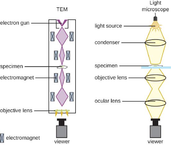
The TEM is somewhat analogous to the brightfield light microscope in terms of the way it functions (Figure \(\PageIndex{11}\)); a beam of energy passes through a specimen and is collected by an objective lens. However, rather than a lamp generating visible light focused by a glass lens (i.e., a condenser), the TEM uses an "electron gun" focused by magnetic lenses to project an electron beam through the specimen and onto a detector which captures the image. The image can then be visualized on a computer screen. In TEM, the electron gun, magnetics and specimen are all placed under vacuum. Prior to visualization with a TEM, the specimen must be processed to be extremely thin (20–100 nm thick) and stained with an electron dense material, such as a metal like lead, osmium, or tungsten. Those parts of the specimen stained with these materials will absorb electrons and produce dark regions on the image. Areas of the image where the electron beam passes through can be seen as lighter.

Bottom image - a transmission electron microscope (TEM) image of a eukaryotic cell. (TEM Cell by Klingm01, CC BY-SA 4.0)
Whereas TEM requires very thin sections and allows one to see internal structures such as organelles, the SEM is used to view the surface of a specimen. To do this, an electron beam produces electrons that scan the surface of a sample, creating a highly detailed image with a three-dimensional appearance that is displayed on a monitor (Figure \(\PageIndex{12}\)). In SEM, specimens are dried and prepared with fixatives before being "sputter-coated" with a thin layer of metal such as gold. The atoms in this gold layer interact with the electron beam to produce backscattered electrons, secondary electrons, and X-rays. These signals are processed by the microscope to generate a gray-scale image of the specimen surface that can be left as is, or colorize if desired.

The PCR Machine
A PCR machine, also known as a thermocycler, is a piece of equipment used to amplify DNA through the process called Polymerase Chain Reaction (PCR). The PCR machine cycles through three different temperatures in order to facilitate denaturation of the DNA helix into single strands, anneal primers to the single strands, and extend from the primers to create strands of daughter DNA. Tubes are placed into a metal tube holder designed to quickly and efficiently transfer heat to the tubes. A front display allows for easy creation of modification of the PCR program (Figure \(\PageIndex{13}\)). For more about PCR, go to Chapter 13.2: Lab Technique - Polymerase Chain Reaction.

The Flow Cytometer
A flow cytometer is used to analyze and sort cells in a fluid using specific physical or chemical characteristics. Flow cytometry is essential for cell sorting, cell counting, and biomarker detection. Cells or particles are suspended in a liquid. Fluorescent dyes or antibodies can be added to the sample to label specific cell markers. The flow cytometer focuses the cells in a "single-file stream" that passes in front of a laser. Detectors in the cytometer then gather specific properties of light that is then used to analyze and sort the cells into distinct populations (Figure \(\PageIndex{14}\)). Forward Scatter (FSC) can be used to measure cell size and Side Scatter (SSC) can be used to measure cell granularity. If fluorescent dyes or antibodies are used, fluorescent emissions can be also used to identify specific cell markers. Using these parameters, the flow cytometer can produce graphs plotting SSC vs FSC, SSC vs fluorescence, or FSC vs. fluorescence. Fluorescence can also be used to physically separate the cells into samples for additional analysis through a technique called Fluorescence-Activated Cell Sorting or FACS.

(B) The information obtained by these detectors is processed to produce plots. Specific populations can be isolated through "gating" (black boxes) and the cells inside the gate further analyzed for cell number, size, and fluorescent intensity. (Flow cytometry plots by Patricia Zuk, CC BY 4.0; modified from Flow Cytometry Chart by Charlotte Hayden, CC BY-SA 4.0)
The equipment used in biotechnology is diverse and specialized, reflecting the complexity and precision required in this field. From basic laboratory tools to advanced and specialized machinery, each piece of equipment plays a crucial role in enabling researchers to conduct experiments, analyze data, and produce biotechnological products. Understanding the functions and applications of these tools is essential for anyone working in or studying biotechnology, as they form the foundation for scientific discoveries and technological advancements.
Glossary
Antibody - a Y-shaped protein produced by B cells of the immune system that recognizes and binds to a specific antigen; also called an immunoglobulin
Antigen - a molecule that triggers an immune response
Condenser - a lens system located beneath the microscope stage that focuses and directs light from the microscope’s light source onto the specimen in order to enhance resolution and contrast
Contrast - the difference in light intensity between the specimen and the background; makes structures more visible under the microscope
Electron gun - an instrument used by an electron microscope to create a focused beam of electrons
Flow cytometry - a lab technique used to analyze and measure the physical and chemical characteristics of a cell population; uses a piece of equipment called a flow cytometer
Fluorescence - the property of a substance to absorb light at one wavelength and emit it at a longer wavelength
Forward scatter - a flow cytometry parameter that refers to the light scattered in the same direction as the laser beam; generally proportional to the size of the cell or particle and is used to help distinguish large cells from small cells
Magnification - how much larger an object is compared to its actual size
Microscope - an instrument used to magnify an object; classified into two major types - light and electron
Microscopy - the technique of using microscopes to observe objects and structures that are too small to be seen with the naked eye
Resolution - the ability of a microscope to distinguish two close points as separate; higher resolution means finer detail can be observed
Side scatter - a flow cytometry parameter that refers to the light that is scattered at a 90° angle to the laser beam; it reflects the granularity or internal complexity of the cell, such as the presence of granules or organelles
Thermocycler - an instrument used to amplify a fragment of DNA; also called a PCR machine
Attributions
Figures adapted from OpenStax Microbiology, CC BY 4.0
- Figure \(\PageIndex{1}\)
- Figure \(\PageIndex{2}\)
- Figure \(\PageIndex{3}\)
- Figure \(\PageIndex{4}\)(in part)
- Figure \(\PageIndex{5}\)
- Figure \(\PageIndex{7}\)
- Figure \(\PageIndex{10}\)
- Figure \(\PageIndex{11}\)(in part)
- Figure \(\PageIndex{12}\)