
15: GFP Fusion Proteins
- Page ID
- 141657
\( \newcommand{\vecs}[1]{\overset { \scriptstyle \rightharpoonup} {\mathbf{#1}} } \)
\( \newcommand{\vecd}[1]{\overset{-\!-\!\rightharpoonup}{\vphantom{a}\smash {#1}}} \)
\( \newcommand{\dsum}{\displaystyle\sum\limits} \)
\( \newcommand{\dint}{\displaystyle\int\limits} \)
\( \newcommand{\dlim}{\displaystyle\lim\limits} \)
\( \newcommand{\id}{\mathrm{id}}\) \( \newcommand{\Span}{\mathrm{span}}\)
( \newcommand{\kernel}{\mathrm{null}\,}\) \( \newcommand{\range}{\mathrm{range}\,}\)
\( \newcommand{\RealPart}{\mathrm{Re}}\) \( \newcommand{\ImaginaryPart}{\mathrm{Im}}\)
\( \newcommand{\Argument}{\mathrm{Arg}}\) \( \newcommand{\norm}[1]{\| #1 \|}\)
\( \newcommand{\inner}[2]{\langle #1, #2 \rangle}\)
\( \newcommand{\Span}{\mathrm{span}}\)
\( \newcommand{\id}{\mathrm{id}}\)
\( \newcommand{\Span}{\mathrm{span}}\)
\( \newcommand{\kernel}{\mathrm{null}\,}\)
\( \newcommand{\range}{\mathrm{range}\,}\)
\( \newcommand{\RealPart}{\mathrm{Re}}\)
\( \newcommand{\ImaginaryPart}{\mathrm{Im}}\)
\( \newcommand{\Argument}{\mathrm{Arg}}\)
\( \newcommand{\norm}[1]{\| #1 \|}\)
\( \newcommand{\inner}[2]{\langle #1, #2 \rangle}\)
\( \newcommand{\Span}{\mathrm{span}}\) \( \newcommand{\AA}{\unicode[.8,0]{x212B}}\)
\( \newcommand{\vectorA}[1]{\vec{#1}} % arrow\)
\( \newcommand{\vectorAt}[1]{\vec{\text{#1}}} % arrow\)
\( \newcommand{\vectorB}[1]{\overset { \scriptstyle \rightharpoonup} {\mathbf{#1}} } \)
\( \newcommand{\vectorC}[1]{\textbf{#1}} \)
\( \newcommand{\vectorD}[1]{\overrightarrow{#1}} \)
\( \newcommand{\vectorDt}[1]{\overrightarrow{\text{#1}}} \)
\( \newcommand{\vectE}[1]{\overset{-\!-\!\rightharpoonup}{\vphantom{a}\smash{\mathbf {#1}}}} \)
\( \newcommand{\vecs}[1]{\overset { \scriptstyle \rightharpoonup} {\mathbf{#1}} } \)
\(\newcommand{\longvect}{\overrightarrow}\)
\( \newcommand{\vecd}[1]{\overset{-\!-\!\rightharpoonup}{\vphantom{a}\smash {#1}}} \)
\(\newcommand{\avec}{\mathbf a}\) \(\newcommand{\bvec}{\mathbf b}\) \(\newcommand{\cvec}{\mathbf c}\) \(\newcommand{\dvec}{\mathbf d}\) \(\newcommand{\dtil}{\widetilde{\mathbf d}}\) \(\newcommand{\evec}{\mathbf e}\) \(\newcommand{\fvec}{\mathbf f}\) \(\newcommand{\nvec}{\mathbf n}\) \(\newcommand{\pvec}{\mathbf p}\) \(\newcommand{\qvec}{\mathbf q}\) \(\newcommand{\svec}{\mathbf s}\) \(\newcommand{\tvec}{\mathbf t}\) \(\newcommand{\uvec}{\mathbf u}\) \(\newcommand{\vvec}{\mathbf v}\) \(\newcommand{\wvec}{\mathbf w}\) \(\newcommand{\xvec}{\mathbf x}\) \(\newcommand{\yvec}{\mathbf y}\) \(\newcommand{\zvec}{\mathbf z}\) \(\newcommand{\rvec}{\mathbf r}\) \(\newcommand{\mvec}{\mathbf m}\) \(\newcommand{\zerovec}{\mathbf 0}\) \(\newcommand{\onevec}{\mathbf 1}\) \(\newcommand{\real}{\mathbb R}\) \(\newcommand{\twovec}[2]{\left[\begin{array}{r}#1 \\ #2 \end{array}\right]}\) \(\newcommand{\ctwovec}[2]{\left[\begin{array}{c}#1 \\ #2 \end{array}\right]}\) \(\newcommand{\threevec}[3]{\left[\begin{array}{r}#1 \\ #2 \\ #3 \end{array}\right]}\) \(\newcommand{\cthreevec}[3]{\left[\begin{array}{c}#1 \\ #2 \\ #3 \end{array}\right]}\) \(\newcommand{\fourvec}[4]{\left[\begin{array}{r}#1 \\ #2 \\ #3 \\ #4 \end{array}\right]}\) \(\newcommand{\cfourvec}[4]{\left[\begin{array}{c}#1 \\ #2 \\ #3 \\ #4 \end{array}\right]}\) \(\newcommand{\fivevec}[5]{\left[\begin{array}{r}#1 \\ #2 \\ #3 \\ #4 \\ #5 \\ \end{array}\right]}\) \(\newcommand{\cfivevec}[5]{\left[\begin{array}{c}#1 \\ #2 \\ #3 \\ #4 \\ #5 \\ \end{array}\right]}\) \(\newcommand{\mattwo}[4]{\left[\begin{array}{rr}#1 \amp #2 \\ #3 \amp #4 \\ \end{array}\right]}\) \(\newcommand{\laspan}[1]{\text{Span}\{#1\}}\) \(\newcommand{\bcal}{\cal B}\) \(\newcommand{\ccal}{\cal C}\) \(\newcommand{\scal}{\cal S}\) \(\newcommand{\wcal}{\cal W}\) \(\newcommand{\ecal}{\cal E}\) \(\newcommand{\coords}[2]{\left\{#1\right\}_{#2}}\) \(\newcommand{\gray}[1]{\color{gray}{#1}}\) \(\newcommand{\lgray}[1]{\color{lightgray}{#1}}\) \(\newcommand{\rank}{\operatorname{rank}}\) \(\newcommand{\row}{\text{Row}}\) \(\newcommand{\col}{\text{Col}}\) \(\renewcommand{\row}{\text{Row}}\) \(\newcommand{\nul}{\text{Nul}}\) \(\newcommand{\var}{\text{Var}}\) \(\newcommand{\corr}{\text{corr}}\) \(\newcommand{\len}[1]{\left|#1\right|}\) \(\newcommand{\bbar}{\overline{\bvec}}\) \(\newcommand{\bhat}{\widehat{\bvec}}\) \(\newcommand{\bperp}{\bvec^\perp}\) \(\newcommand{\xhat}{\widehat{\xvec}}\) \(\newcommand{\vhat}{\widehat{\vvec}}\) \(\newcommand{\uhat}{\widehat{\uvec}}\) \(\newcommand{\what}{\widehat{\wvec}}\) \(\newcommand{\Sighat}{\widehat{\Sigma}}\) \(\newcommand{\lt}{<}\) \(\newcommand{\gt}{>}\) \(\newcommand{\amp}{&}\) \(\definecolor{fillinmathshade}{gray}{0.9}\)Summary
Fluorescent proteins like GFP can be fused to other proteins of interest to visually track the protein’s location in living cells.
Also known as
GFP-tagged proteins, fluorescently-tagged proteins
Note: GFP variants are now available in every color of the rainbow, and they can also be used for this application.
Samples needed
In order to attach a GFP tag to a protein, a cDNA sequence encoding the protein must be available for molecular cloning.
Once the gene for the GFP-tagged protein is introduced into a cell or organism, the location can be visualized even in live cells. Cells can also be fixed and fluorescent signal will persist.
Method
In order to generate a GFP fusion protein, a cDNA that encodes the protein of interest must be available or obtainable. Then, through molecular cloning, the cDNA for GFP must be cloned upstream or downstream of the cDNA for the protein of interest, in frame, creating a fusion protein.
Next, the modified DNA must be introduced into the cell of interest. This can be done through a number of methods, either transient or stable transfection, CRISPR, or others.
Finally, the GFP fusion protein can be tracked via fluorescent microscopy on live cells. The GFP fusion protein can also be tracked in multiple other ways, essentially by using the GFP portion of the protein in the same way as one would use an epitope tag. For instance, if a researcher wanted to immunoprecipitate the protein of interest, they could use an antibody against either the protein of interest, or against GFP.
Controls
GFP is not a small addition to a protein! Therefore, every effort should be made to determine whether the addition of the GFP to the protein of interest affects the protein’s normal function.
Interpretation
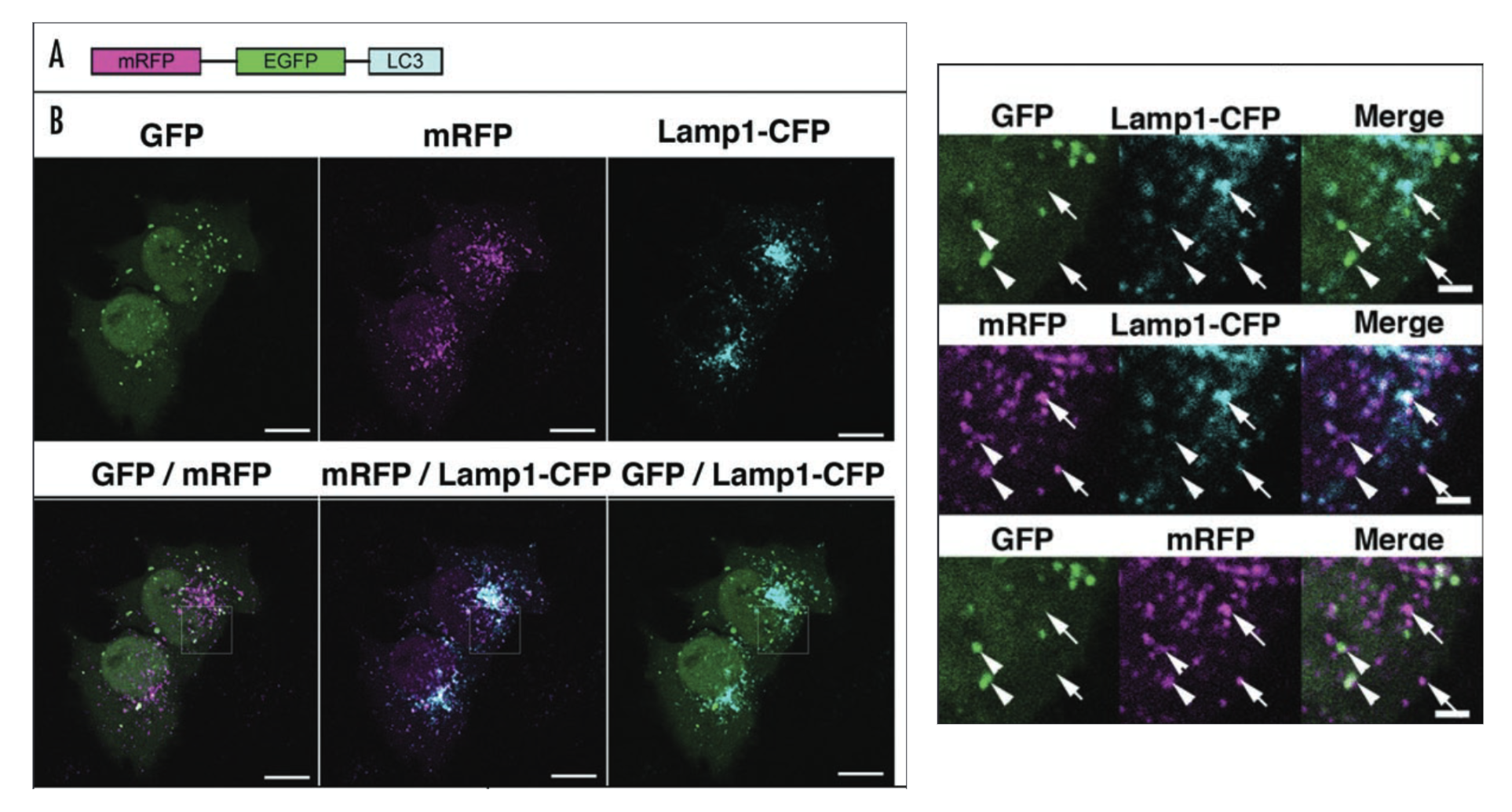
Figure 1. Confocal microscopy of HeLa cells transfected with various fluorescent protein fusions. Relevant section of caption for published figure reads: “The GFP and mRFP signals of tfLC3 show different localization patterns. (A) Diagram of tfLC3 structure. (B) HeLa cells were cotransfected with plasmids expressing either tfLC3 or Lamp1‑CFP.Twenty‑four hours after the transfection, the cells were starved in Hanks’ solution for 2 hours, fixed and analyzed by microscopy. The lower panels are a higher magnification of the upper panels. Barindicates 10 mm in the upper panels and 2 mm in the lower panels. Arrows in the lower panels point to typical examples of colocalized signals of mRFP and Lamp1. Arrowheads point to typical examples of colocalized particles of GFP and mRFP signals.” “Figure 4” by Kimura et al.[1] [Image description]
| mRFP | GFP | Lamp1 | |
|---|---|---|---|
| mRFP signals | N/A | 24 ± 5 | 67 ± 12 |
| GFP signals | 86 ± 4.6 | N/A | 6.7 ± 2.6 |
Autophagy is a process by which starving cells engulf some of their cytoplasm within a double-membrane vesicle to recycle the contents in order to stave off cell death. The initial vesicle is called an autophagosome. Eventually, these vesicles fuse with lysosomes, and form the acidic autolysosome. In Kimura et al., the authors describe the development of a tool for interrogating the maturation pathway from autophagosomes to autolysosomes. This tool is a “tandem fluorescent” LC3 protein, the LC3 protein fused with both monomeric red fluorescent protein (mRFP) and green fluorescent protein (GFP). They call this tfLC3. Before their study, it was already known that LC3 is associated with autophagosome membranes from the earliest stages of their formation. In the figure, we also see another fusion protein: Lamp1-CFP. CFP is cyan fluorescent protein, and Lamp1 is a protein found in the lysosome, and eventually the autolysosome.
Earlier in their study, Kimura et al. showed that mRFP-LC3 showed more puncta in cells than GFP-LC3 and hypothesized that this could be due to the less stable GFP denaturing in the acidic environment of the autolysosome, whereas mRFP remained stable there. To test this hypothesis, they tested co-localization of ftLC3 (marks autophagosomes and autolysosomes) with Lamp1-CFP (marks lysosomes and autolysosomes). The figure above shows both the microscopy images and the quantification (Table 1) of co-localization from those images. Nearly all the GFP signal co-localized with mRFP signal, which is expected, since both signals come from the same fusion protein. However, a significant proportion of the mRFP signal does not co-localize with the GFP signal, implying that some fraction of the fusion proteins have lost GFP signal but maintained mRFP signal, which is consistent with the authors’ hypothesis that GFP was denaturing in a location where mRFP was still folded. They confirmed that this location was the autolysosome by showing that mRFP co-localized with Lamp1-CFP in locations where GFP signal was absent.
This is also a good example of why it’s so important to test your assumption that your protein of interest is present exactly where you see a signal from your fusion protein! LC3 is present in the autolysosomes, but the GFP signal is lost. In this case, the authors did their due diligence and figured this out. In fact, they were actually able to exploit this characteristic to make a reporter protein, tfLC3, which can now be used as a useful tool to determine whether various experimental conditions affect the autophagosome, the autolysosome, or both.
Image Descriptions
Figure 1 image description:
Panel A: A schematic of a single fusion protein containing mRFP, GFP, and LC3.
Panel B: A series of fluorescent microscopy images. All show fluorescent signals in puncta spread around 2 cells. In all cases, some of the puncta co-localize, but not all. Images shown are: GFP, mRFP, Lamp1-CFP, GFP/mRFP merge, mRFP/Lamp1-CFP merge, GFP/Lamp1-CFP merge. There are also insets with greater magnification showing a few puncta that exhibit co-localization. Quantification of extent of co-localization in Table 1. ↵
Thumbnail
"Green fluorescent protein image of the mouse cochlea.jpg"↗ by Atwiki111 is licensed under CC BY-SA 4.0↗.
Description: Green fluorescent protein image of the mouse cochlea.
Author
Katherine Mattaini, Tufts University
-
Kimura, S., T. Noda, and T. Yoshimori. 2007. Dissection of the Autophagosome Maturation Process by a Novel Reporter Protein, Tandem Fluorescent-Tagged LC3. Autophagy 3:452–460. ↵