
2.6: Laboratory Activities and Assignment
- Page ID
- 53542

\( \newcommand{\vecs}[1]{\overset { \scriptstyle \rightharpoonup} {\mathbf{#1}} } \)
\( \newcommand{\vecd}[1]{\overset{-\!-\!\rightharpoonup}{\vphantom{a}\smash {#1}}} \)
\( \newcommand{\id}{\mathrm{id}}\) \( \newcommand{\Span}{\mathrm{span}}\)
( \newcommand{\kernel}{\mathrm{null}\,}\) \( \newcommand{\range}{\mathrm{range}\,}\)
\( \newcommand{\RealPart}{\mathrm{Re}}\) \( \newcommand{\ImaginaryPart}{\mathrm{Im}}\)
\( \newcommand{\Argument}{\mathrm{Arg}}\) \( \newcommand{\norm}[1]{\| #1 \|}\)
\( \newcommand{\inner}[2]{\langle #1, #2 \rangle}\)
\( \newcommand{\Span}{\mathrm{span}}\)
\( \newcommand{\id}{\mathrm{id}}\)
\( \newcommand{\Span}{\mathrm{span}}\)
\( \newcommand{\kernel}{\mathrm{null}\,}\)
\( \newcommand{\range}{\mathrm{range}\,}\)
\( \newcommand{\RealPart}{\mathrm{Re}}\)
\( \newcommand{\ImaginaryPart}{\mathrm{Im}}\)
\( \newcommand{\Argument}{\mathrm{Arg}}\)
\( \newcommand{\norm}[1]{\| #1 \|}\)
\( \newcommand{\inner}[2]{\langle #1, #2 \rangle}\)
\( \newcommand{\Span}{\mathrm{span}}\) \( \newcommand{\AA}{\unicode[.8,0]{x212B}}\)
\( \newcommand{\vectorA}[1]{\vec{#1}} % arrow\)
\( \newcommand{\vectorAt}[1]{\vec{\text{#1}}} % arrow\)
\( \newcommand{\vectorB}[1]{\overset { \scriptstyle \rightharpoonup} {\mathbf{#1}} } \)
\( \newcommand{\vectorC}[1]{\textbf{#1}} \)
\( \newcommand{\vectorD}[1]{\overrightarrow{#1}} \)
\( \newcommand{\vectorDt}[1]{\overrightarrow{\text{#1}}} \)
\( \newcommand{\vectE}[1]{\overset{-\!-\!\rightharpoonup}{\vphantom{a}\smash{\mathbf {#1}}}} \)
\( \newcommand{\vecs}[1]{\overset { \scriptstyle \rightharpoonup} {\mathbf{#1}} } \)
\( \newcommand{\vecd}[1]{\overset{-\!-\!\rightharpoonup}{\vphantom{a}\smash {#1}}} \)
\(\newcommand{\avec}{\mathbf a}\) \(\newcommand{\bvec}{\mathbf b}\) \(\newcommand{\cvec}{\mathbf c}\) \(\newcommand{\dvec}{\mathbf d}\) \(\newcommand{\dtil}{\widetilde{\mathbf d}}\) \(\newcommand{\evec}{\mathbf e}\) \(\newcommand{\fvec}{\mathbf f}\) \(\newcommand{\nvec}{\mathbf n}\) \(\newcommand{\pvec}{\mathbf p}\) \(\newcommand{\qvec}{\mathbf q}\) \(\newcommand{\svec}{\mathbf s}\) \(\newcommand{\tvec}{\mathbf t}\) \(\newcommand{\uvec}{\mathbf u}\) \(\newcommand{\vvec}{\mathbf v}\) \(\newcommand{\wvec}{\mathbf w}\) \(\newcommand{\xvec}{\mathbf x}\) \(\newcommand{\yvec}{\mathbf y}\) \(\newcommand{\zvec}{\mathbf z}\) \(\newcommand{\rvec}{\mathbf r}\) \(\newcommand{\mvec}{\mathbf m}\) \(\newcommand{\zerovec}{\mathbf 0}\) \(\newcommand{\onevec}{\mathbf 1}\) \(\newcommand{\real}{\mathbb R}\) \(\newcommand{\twovec}[2]{\left[\begin{array}{r}#1 \\ #2 \end{array}\right]}\) \(\newcommand{\ctwovec}[2]{\left[\begin{array}{c}#1 \\ #2 \end{array}\right]}\) \(\newcommand{\threevec}[3]{\left[\begin{array}{r}#1 \\ #2 \\ #3 \end{array}\right]}\) \(\newcommand{\cthreevec}[3]{\left[\begin{array}{c}#1 \\ #2 \\ #3 \end{array}\right]}\) \(\newcommand{\fourvec}[4]{\left[\begin{array}{r}#1 \\ #2 \\ #3 \\ #4 \end{array}\right]}\) \(\newcommand{\cfourvec}[4]{\left[\begin{array}{c}#1 \\ #2 \\ #3 \\ #4 \end{array}\right]}\) \(\newcommand{\fivevec}[5]{\left[\begin{array}{r}#1 \\ #2 \\ #3 \\ #4 \\ #5 \\ \end{array}\right]}\) \(\newcommand{\cfivevec}[5]{\left[\begin{array}{c}#1 \\ #2 \\ #3 \\ #4 \\ #5 \\ \end{array}\right]}\) \(\newcommand{\mattwo}[4]{\left[\begin{array}{rr}#1 \amp #2 \\ #3 \amp #4 \\ \end{array}\right]}\) \(\newcommand{\laspan}[1]{\text{Span}\{#1\}}\) \(\newcommand{\bcal}{\cal B}\) \(\newcommand{\ccal}{\cal C}\) \(\newcommand{\scal}{\cal S}\) \(\newcommand{\wcal}{\cal W}\) \(\newcommand{\ecal}{\cal E}\) \(\newcommand{\coords}[2]{\left\{#1\right\}_{#2}}\) \(\newcommand{\gray}[1]{\color{gray}{#1}}\) \(\newcommand{\lgray}[1]{\color{lightgray}{#1}}\) \(\newcommand{\rank}{\operatorname{rank}}\) \(\newcommand{\row}{\text{Row}}\) \(\newcommand{\col}{\text{Col}}\) \(\renewcommand{\row}{\text{Row}}\) \(\newcommand{\nul}{\text{Nul}}\) \(\newcommand{\var}{\text{Var}}\) \(\newcommand{\corr}{\text{corr}}\) \(\newcommand{\len}[1]{\left|#1\right|}\) \(\newcommand{\bbar}{\overline{\bvec}}\) \(\newcommand{\bhat}{\widehat{\bvec}}\) \(\newcommand{\bperp}{\bvec^\perp}\) \(\newcommand{\xhat}{\widehat{\xvec}}\) \(\newcommand{\vhat}{\widehat{\vvec}}\) \(\newcommand{\uhat}{\widehat{\uvec}}\) \(\newcommand{\what}{\widehat{\wvec}}\) \(\newcommand{\Sighat}{\widehat{\Sigma}}\) \(\newcommand{\lt}{<}\) \(\newcommand{\gt}{>}\) \(\newcommand{\amp}{&}\) \(\definecolor{fillinmathshade}{gray}{0.9}\)Laboratory Activities and Assignment
Part 1: Getting to Know the Microscope
1. Label the parts of the compound microscope below using the terms listed.
|
|
|

2. Match the names of the microscope parts with their descriptions:
|
___ coarse adjustment knob ___ arm ___ condenser ___ eyepiece (ocular) ___ iris/diaphragm ___ nosepiece ___ objective lens ___ stage ___ light source ___ stage clip ___ fine adjustment knob |
A. Increases the light intensity B. Platform that supports the microscope slide C. Concentrates light onto the specimen D. Shines through the specimen to carry the specimen image to the viewer E. Causes the stage to move upward or downward at a fast rate and is used to focus on a specimen F. After the light passes through the specimen, it next enters this lens system G. Causes the stage to move upward or downward at a slow rate and is used to focus on a specimen H. Holds a microscope slide in position I. Contain a lens at the top of it J. Serves as a handle to carry the microscope K. Part of which the objective lenses are attached |
3. Pick up your microscope and physically move it to a new location. Bring it close enough that you can look into it comfortably from where you are sitting. Arrange it so that the stage is facing you and the eyepiece is rotated towards you. What part of the microscope did you grab in order to pick it up and move it?
4. Where are the locations of the two stage adjustment knobs on your microscope?
5. Where is the location of the coarse focus knob?
6. Where is the location of the fine focus knob?
7. Is there a condenser adjustment knob? If so, where is it located?
8. Find the diaphragm lever. Looking in the hole in the center of the stage, what happens when you move the diaphragm lever clockwise?
9. Still looking down at the hole in the center of the stage, what happens when you slide the diaphragm lever counterclockwise?
Part 2: Magnifications of the Microscope
1. Write down the magnification factor for the eyepiece lenses (ocular lenses) on the microscope in front of you.
2. Using the microscope in front of you, write out all the words and numbers written on each objective on your microscope. There are probably three or four objectives. Start with the smallest objective and move through them in order of increasing size:
- Objective one:
- Objective two:
- Objective three:
- Objective four:
3. In the above list, for each objective, circle just the magnification factor for that objective. Remember, the magnifying factor is a whole number, and differs for each different objective.
4. Write down the total magnification (ocular lens magnification x objective lens magnification) when using each objective on the microscope in front of you.
- Total magnification - objective one:
- Total magnification - objective two:
- Total magnification - objective three:
- Total magnification - objective four:
**Magnified images in textbooks, activities, and assignments always refer to the TOTAL magnification. To determine the objective lens you will need to use when given instructions in future labs, multiply the magnification written on each objective by the magnification of the ocular lens to determine the total magnification.**
5. If you observed two features on a slide with your naked eye that were 0.5 mm apart, how far apart would they appear to be if you observed them with the microscope in front of you, using the second objective?
Part 3: Comparing the Real Image (Naked Eye) with the Magnified Virtual Image
1. Get an “e” slide. If it is already under your microscope, rotate the lowest-power objective into place, use the coarse focus to lower the stage, and remove the slide.
2. Look at the unmagnified “e” on the slide by eye. Rotate the slide around in your hand so that the “e” is right side up. Now clip the slide onto the microscope stage with the stage clips so that the “e” is facing you right side up when you look at it with your unaided eye.
3. In the right-hand circle below, draw what the “e” looks like when you are looking at it right side up with the unaided eye. Assume the circle below is the size of the entire coverslip. Draw the “e” you see unaided in the correct proportion to the coverslip. (The unmagnified “e” will take up a tiny portion of the coverslip area.)
magnified "e" "e" with the unaided eye

4. Position the slide into slide clips on your microscope stage so that the “e” is still facing you right side up. Get the “e” into your field of view and in focus.
5. In the left-hand circle above, draw what the “e” looks like when viewing it through the microscope under the lowest-power objective. Under the circle, write the total magnification of the image.
6. When viewed under a microscope, how is a specimen rotated?
7. Look at the stage and slide directly (not through the eyepieces). Move the stage control knob that causes the slide to move away from you on the stage, then move it back to its original position.
8. Now move the stage control knob the exact same way you just did, but view the “e” through the eyepiece. When the stage is moving away from you, what direction does the virtual image appear to be moving?
9. Again, look at the stage and slide directly (not through the eyepiece.) This time, move the stage control knob that causes the slide to move to your right, then move it back to its original position.
10.Now move the stage control knob the exact same way you just did, but view the “e” through the eyepiece. When the stage is moving to your right, what direction does the virtual image appear to be moving?
11.The field of view is the entire area you can see when looking through an eyepiece. Use the stage control knobs to move the virtual image of your “e” to one side of the field of view. Keep most of the “e” in the field of view, but move it to one side or the other.
12.Now switch to the next-power objective. Do not skip objectives. To get to the next-power objective, and not the highest-power objective, which way did you have to rotate the objectives, clockwise or counterclockwise?
13.Using only the fine focus knob (you do NOT use the coarse focus knob on any objective other than the lowest objective), get the “e” in focus.
14.Move away from the eyepieces and look at the distance between the slide and the bottom of the objective. Rotate back to the lowest power objective. Now rotate to the next objective (do not rotate to the highest-power objective by accident). Now rotate to the third-highest objective. What happens to the distance between the slide and the bottom of the objective as you rotate to higher power objectives?
15.With the third-highest power objective still in place, how much space is there between the slide and the bottom of the objective?
16.Notice there is a danger of smashing the objective lens into the slide if you were to use the coarse focus. Why are you instructed to only use the coarse focus with the lowest- power objective?
Part 4: Making Illustrations of Magnified Specimens
Instructions for Making Illustrations of Magnified Specimens
You do not have to be a great artist to make a diagram of the cells and structures you see under a microscope. You only have to be careful to draw something that is approximately the same size and shape as what you see. Follow the following guidelines:
- Only draw what you actually see. Even if you expect to see something, if it is not there you should not draw it. Do not base your drawings on what the textbook or some other source tells you should be there. Do not draw things in the shapes that texts or other sources tell you to expect unless you actually see those shapes.
- Keep things as simple as possible. Draw strong unbroken lines. Avoid shading or cross- hatching unless there is a very good reason to add them.
- Feel free to simplify reality by leaving out unnecessary details. Draw what is of interest, but leave out background material, debris, or any other distracting items. Just be careful that, if you are leaving something out, that it isn’t something that is an important part of what you are drawing.
You should always have a basic understanding of what you are looking for before looking in the microscope. Tissues and other microscopic specimens can be confusing and cluttered. If you know in general what you are looking for, and, sometimes more importantly, what you are not looking for, it will make it much easier to find what you want to draw and it will make it much easier to decide how to draw it.
Just remember, what you see under the microscope may look quite different from the perfect specimens that are usually found in the figures put into textbooks and websites. Use the idealized images to track down what you are looking for, but draw the specimen as it actually is, regardless of your expectations.
For instance, in most textbooks, neurons, the most common cell found in nervous tissue, are drawn to look like variations of the drawing in the figure below:

Above: (A) Textbook illustration of a neuron. (B) Microscopic image of a neuron.
In the typical diagram of a neuron that appears in texts and on websites, there usually is a clear nucleus, and often a nucleolus visible, too. The dendrites are typically short and branched. There almost always is a single, easily-identifiable axon that is longer than all the dendrites and branches as it ends. An actual neuron as viewed through a microscope may look different from a “typical” neuron. In fact, often actual specimens look very little like their textbook counterparts. Draw what you see, not what you think you are supposed to see. Just make sure you are looking at what you are supposed to be finding (for instance, a neuron and not a piece of dirt or cell debris), and then draw it as it is.

Above: (A) Textbook illustration of a neuron. (B) Microscopic image of a neuron.
Most students feel they “cannot draw” and are reluctant to sketch what they are seeing under a microscope. Don’t let what you believe to be a lack of artistic skills stop you! Use the following tips:
- Draw an outline that approximates the item you want to draw. Don’t obsess about making it match perfectly. Approximate is ok.
- Try to get the proportions approximately right. If something is half as big, or as third as big, as something else, make it that way in the drawing, too.
- Do not draw everything you see. Improve on reality by only drawing the parts of the specimen you are interested in. You do not have to draw every bit of debris or dirt. Decide what the important parts of your specimen are and draw only those.
Practice Making Illustrations of Magnified Specimens
1. Get a human blood smear slide. Rotate your lowest power objective into place on your microscope.
2. Follow the directions for focusing on a sample until you are viewing the blood smear at 400x magnification (using the 40x objective).
3. You will see mostly red blood cells. They will probably be pinkish and they will be the circles without nuclei. Occasionally, some will appear to have blank circles in their centers, but these are not nuclei. If you search around your slide using your stage controls, you will find the rare circular cells with nuclei. These are white blood cells. There will be less than one white blood cell for every 100 red blood cells. These white blood cells will probably be light blue or grey and have purple or dark blue nuclei. The nuclei of white blood cells will not always be round.
4. Find a section of your slide with two or more white blood cells among all the red blood cells.
5. In the circle below, draw four or five representative red blood cells (do not draw all the red blood cells you see) and draw all the white blood cells in your field of view. Pay careful attention to drawing the white blood cell nuclei as accurately as possible.

Part 5: Approximating the Size of a Magnified Specimen
Measure the Microscopic Fields of View
1. Set the TOTAL magnification of the microscope to 40x or the lowest magnification objective.
2. Place a transparent ruler across the stage of the microscope on top of the stage clips so that the metric side of the ruler is in the light (metric ruler lines can be seen when you look through the oculars).
3. Use the course focus knob to focus on the ruler.
4. Count the number of spaces between the lines on the ruler (each space is a millimeter (mm)) to determine the length of the diameter of the field of view of the compound microscope (see figure below). Record this length in the table below.
5. Switch the microscope to the next highest magnification objective (commonly 100x TOTAL magnification) and adjust the focus using the fine focus knob.

6. Count the number of spaces between the lines on the ruler to determine the length of the diameter of the field of view of the compound microscope. Record this length in the table below.
7. Move to the next highest magnification (usually 400x total magnification) and adjust the focus using the fine focus knob. Can you see the spaces/lines on the ruler to measure the diameter?
8. Calculate the diameter at the magnification from step 7. The difference between 40x and 400x is a magnitude of 10, so there will be a magnitude of 10 difference between the diameter of the field of view at 40x and 400x. To calculate, the diameter of the field of view at 40x is divided by 10 to determine the field of view diameter at 400x:
field of view at 400x (mm) = field of view at 40x (mm) ÷ 10
9. Convert the field of view diameters from mm to µm and record in the table below.
|
TOTAL objective magnification |
Field of view diameter (mm) |
Field of view diameter (µm) There are 1,000 µm in each 1 mm. |
|---|---|---|
10. Describe the relationship between the total magnification and the field of view diameter. Use your answers from the table above.
Use Field of View Diameters to Approximate Sizes of Microscopic Objects
Imagine the black circle in the figure below is the field of view of the microscope. The blue line across shows the entire diameter of the field of view. There is no actual diameter line in the field of view, nor are there markings that show the percentage of the diameter as shown below - this is where your imagination must come into play to estimate the size of objects in the microscope.
The yellow circle below represents some object magnified by the microscope that you wish to measure. You can see that the yellow circle takes up about 50% of the entire diameter at this magnification. To estimate the size of the yellow circle, use the table above with the diameters of the field of view using the following process:
1. Determine what the total magnification you are viewing the object with and use the table above to determine what the diameter of the field of view is at that total magnification.
2. Estimate the percentage of the diameter of field of view the object you are measuring takes up.
3. Multiply the diameter of the field of view at that magnification in micrometers (µm) by the percentage you determined in part 2:
estimate of object size (µm) = % of field of view diameter x diameter of the field of view at that mag. (µm)
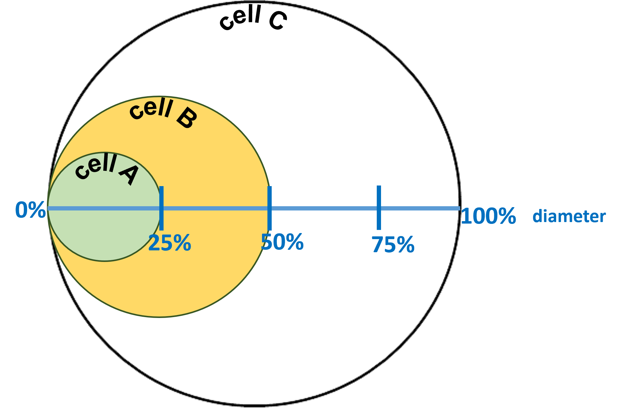
For example, let's say that the yellow circle is an object magnified by 400x (total magnification). Let's say that in the previous section you calculated the diameter of the field of view at 400x to be 0.5 mm or 500 µm (this value may or may not correspond with your actual measurements and calculations from above - this is for this example only). It is estimated that at 400x, the yellow circle takes up 50% of the diameter of the field of view. The size of the yellow circle is therefore calculated:
Yellow circle size (µm) = 50% x 500 µm = 250 µm
Let's do one more example to show how the magnification changes the calculation.
Use the green circle above to represent another object that is viewed using the microscope at a lower magnification (100x). Let's say in the previous section, it was determined that the diameter of the field of view at 100x was 2 mm or 2,000 µm (this value may or may not correspond with your actual measurements and calculations from above - this is for this example only). It is estimated that at 100x, the green circle is 25% of the diameter of the field of view. The size of the green circle is therefore calculated:
Green circle size (µm) = 25% x 2,000 µm = 500 µm
Use the instructions above to calculate estimated sizes for the objects below at the magnifications given with their corresponding fields of view:

|
Magnification = 2,000x Diameter of field of view = 100 µm Approximate object size = _______µm |
Magnification = 1,500x Diameter of field of view = 300 µm Approximate object size = _______µm |
Magnification = 1,500x Diameter of field of view = 300 µm Approximate object size = _______µm |
Part 6: Examining, Measuring, & Illustrating Magnified Specimens
Examine, Measure, and Illustration the Epithelial Tissue Layer of the Skin
1. Obtain a slide of skin and focus on the sample using the techniques you learned in this laboratory.
2. Identify the epithelial tissue layer of the skin (see figure below) on the slide.

3. Measure the thickness of the epithelial tissue layer of the skin in micrometers (µm) as you learned to do in the previous section. Write your calculation and put your estimated measurement in the space provided:
Estimated thickness of the epithelial tissue layer of the skin:_______ µm
4. Make an illustration of the sample in the space below and indicate the magnification of your illustration:

Examine, Measure, and Illustrate Cheek Epithelial Cells
1. Make a wet mount of cheek epithelial cells. Watch this video for instructions for making a wet mount of cheek epithelial cells.
a. Set a new slide on the benchtop.
b. Put a very small drop of saline (0.85% - 0.9% NaCl) in the center of the slide.
c. GENTLY scrape the inside of your cheek with a toothpick to obtain cheek epithelial cells.
d. Swirl the same side of the toothpick that scraped the inside of your cheek in the drop of saline on the slide.
e. Dispose of the toothpick in a biological waste container or in a container of bleach water.
f. Place one small drop of methylene blue (stain) on top of the saline/cheek cell solution on the slide.
g. Place one edge of a cover slip toward the edge of the fluid on the slide at about a 45 degree angle and dip in the fluid.
h. Release the cover slip onto the fluid on the slide. The fluid should spread out underneath the cover slip.
i. Use a paper towel or KimWipe at the edge of the cover slip to wick off excess fluid.
2. Focus on the cheek epithelial cell sample using the techniques you learned in this laboratory.
3. Identify the cheek epithelial cells on the slide. Make sure you are looking at cheek epithelial cells and not other debris on the slide. See the video linked above to examine what cheek epithelial cells should look like.
4. Measure the size of a cheek epithelial cell in micrometers (µm) as you learned to do in the previous section. Write your calculation and put your estimated measurement in the space provided:
Estimated size of a cheek epithelial cell:_______ µm
5. Make an illustration of the sample in the space below and indicate the magnification of your illustration:
Attributions
Part 1: Getting to Know the Microscope
- "Anatomy and Physiology I Lab" by Victoria Vidal is licensed under CC BY 4.0
- "BIOL 250 Human Anatomy Lab Manual SU 19" by Yancy Aquino, Skyline College is licensed under CC BY-NC-SA 4.0
Part 2: Magnifications of the Microscope
- "BIOL 250 Human Anatomy Lab Manual SU 19" by Yancy Aquino, Skyline College is licensed under CC BY-NC-SA 4.0
Part 3: Comparing the Real Image (Naked Eye) with the Magnified Virtual Image
- "BIOL 250 Human Anatomy Lab Manual SU 19" by Yancy Aquino, Skyline College is licensed under CC BY-NC-SA 4.0
Part 4: Making Illustrations of Magnified Specimens
- "BIOL 250 Human Anatomy Lab Manual SU 19" by Yancy Aquino, Skyline College is licensed under CC BY-NC-SA 4.0
Part 6: Examining, Measuring, & Illustrating Magnified Specimens
- "Anatomy and Physiology Lab Reference" by Laird C Sheldahl, OpenOregonEducational Resources, Mt. Hood Community College is licensed under CC BY-SA 4.0
- "BIOL 250 Human Anatomy Lab Manual SU 19" by Yancy Aquino, Skyline College is licensed under CC BY-NC-SA 4.0