16.2: Mining, Processing, and Generating Electricity
- Page ID
- 31660
Fossil fuels must be extracted or mined before use, and the specific method depends on the type of fossil fuel. Coal and natural gas and primarily used for electricity generation, while petroleum is refined to produce fuel for vehicles, planes, and heating as well as other products.
Coal
Mining
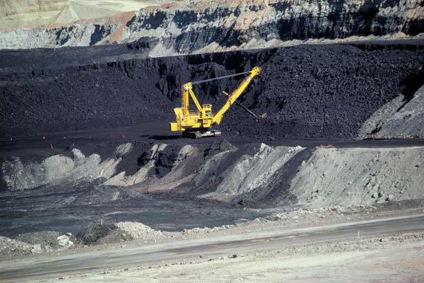
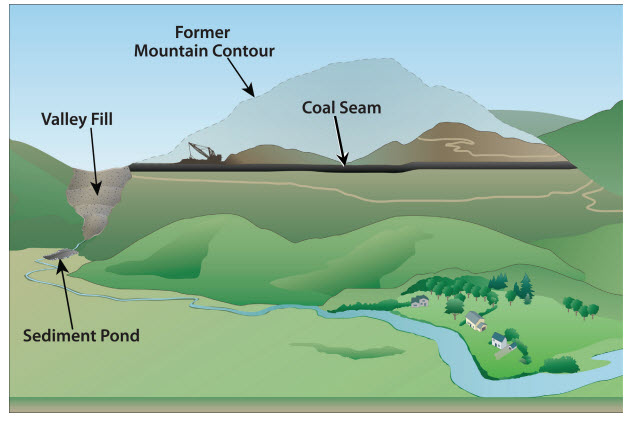
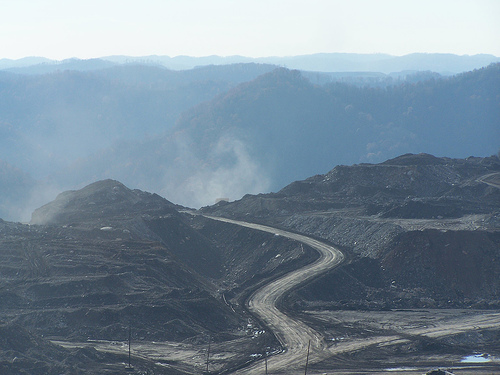
Coal is extracted by two principal methods, of which there are many variants: surface mining or subsurface mining. Surface mining uses large machines to remove the soil and layers of rock known as overburden to expose coal seams that are close to the Earth’s surface (figure \(\PageIndex{a}\)). Strip mining is a type of surface mining in which overburden is sequentially removed from each stretch (strip) of land. Once overburden is removed from the first strip, coal is removed. Overburden from the second strip is then deposited into the first strip, and coal is removed from the second strip. Overburden from the third strip is then placed in the first strip, and so on. Mountaintop removal is a more destructive type of surface mining in which all of the overburden is removed with explosives, revealing the entire coal seam at once (figure \(\PageIndex{b}\)). The large mass of overburden (the mountaintop) is dumped into a nearby valley, and the coal is them removed.
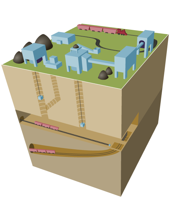
Subsurface mining (deep mining) employs underground tunnels to access deeper deposits (figure \(\PageIndex{c}\)). Some underground mines are thousands of feet deep, and extend for miles. Miners ride elevators down deep mine shafts and travel on small trains in long tunnels to get to the coal. The miners use large machines that dig out the coal. In drift mines, a tunnel is dug horizontally into the side of a mountain. In slope mines, this tunnel is diagonal. In shaft mines, elevators are used to move coal through vertical tunnels.
Processing of Coal
Once mined, coal may go to a preparation plant located near the mining site where it is cleaned and processed to remove impurities such as rocks and dirt, ash, sulfur, and other unwanted materials. This process increases the amount of energy that can be obtained from a unit of coal, known as its heating value.
Transport of Coal
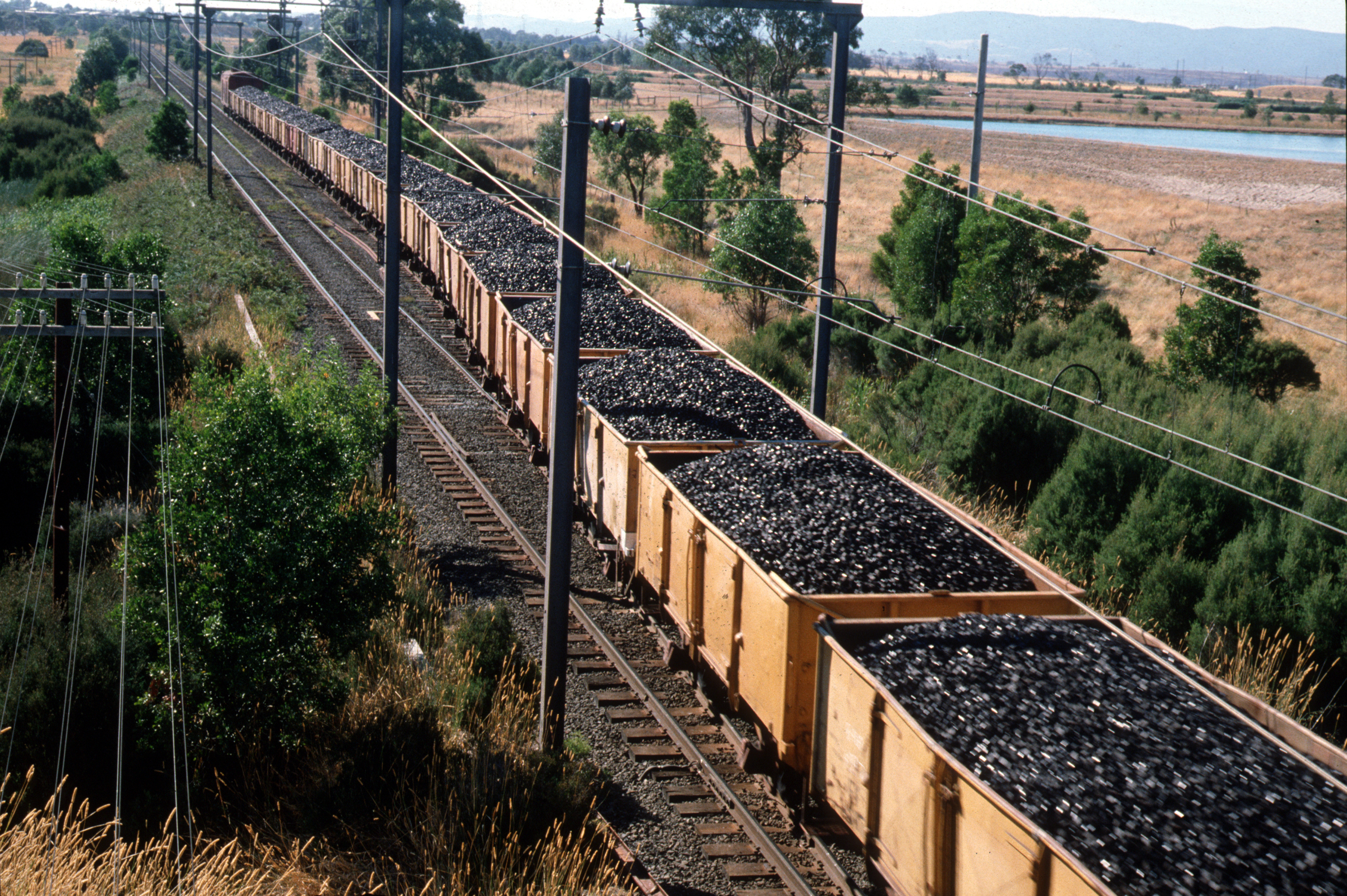
Finally, the mined and processed coal must be transported. Transportation can be more expensive than mining the coal. Nearly 70% of coal delivered in the United States is transported, for at least part of its trip, by train (figure \(\PageIndex{e}\)). Coal can also be transported by barge, ship, or truck. Coal can also be crushed, mixed with water, and sent through a slurry pipeline. Sometimes, coal-fired electric power plants are built near coal mines to lower transportation costs.
Generating Electricity from Coal
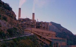
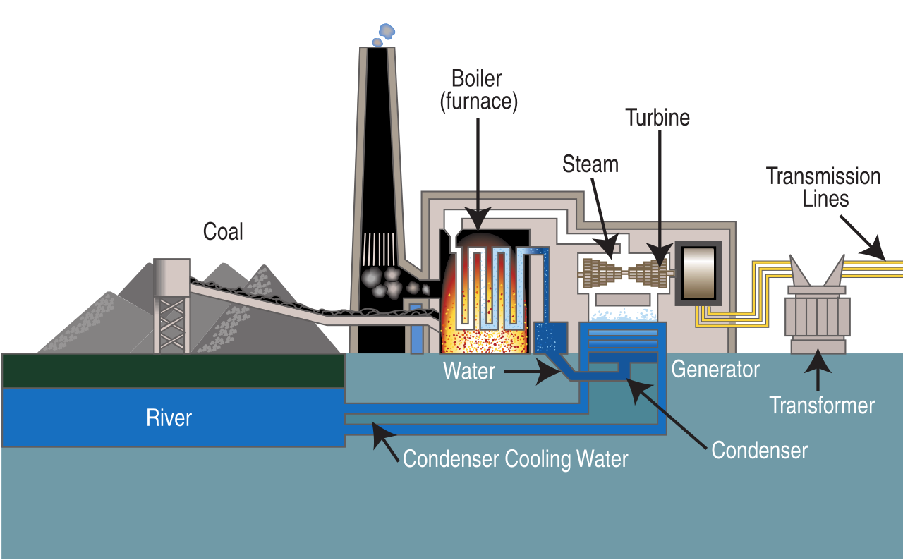
Once at the power plant, coal is first pulverized into a fine powder and then mixed with hot air and blown into a furnace (figure \(\PageIndex{f}\)). This allows for the most complete combustion (burning) and maximum heat release. Purified water, pumped through pipes inside a boiler, is turned into steam by the heat from the combustion of coal. The high pressure of the steam pushing against a series of giant turbine blades turns the turbine shaft. The turbine shaft is connected to the shaft of the generator, where magnets spin within wire coils to produce electricity. After doing its work in the turbine, the steam is drawn into a condenser, a large chamber in the basement of the power plant. In this important step, millions of gallons of cool water from a nearby source (such as a river or lake) are pumped through a network of tubes running through the condenser. The cool water in the tubes converts the steam back into water that can be used over and over again in the plant. The cooling water is returned to its source without any contamination except at a higher temperature than when first extracted from the river or lake.
This video shows how heat energy can be used to generate electricity.
Oil and Natural Gas
Extraction of Conventional Oil and Natural Gas
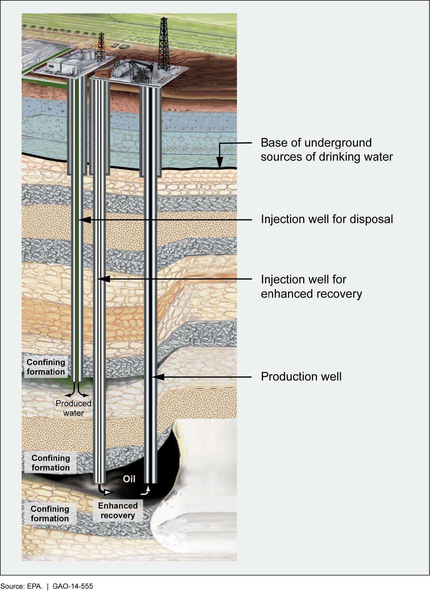
Conventional oil and natural gas are contained under a trap (cap rock). Because natural gas consists of lighter molecules that are in a gaseous form at moderate temperatures, it is found on top of the oil, which may be floating on groundwater. To access conventional oil and natural gas, the trap is first pierced. Initially, they are under high enough pressure, and this drives them out of the well (primary recovery). Next, water (or gas) is injected to force more fossil fuels out (secondary recovery). Finally, enhanced oil recovery (tertiary recovery) may be used to extract further oil by applying heat (injecting steam) or injecting carbon dioxide, other gases, or larger molecules. For example, carbon dioxide causes the oil to thin and expand, making it easier to remove from the rocks. Note that secondary recovery simply increases pressure inside the reservoir whereas tertiary recovery changes the properties of the oil, making it easier to extract (figure \(\PageIndex{g}\)). Each stage of recovery is increasingly expensive, and extraction from a well continues as long as it remains profitable.
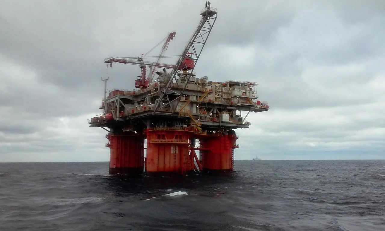
Oil is mainly obtained by drilling either on land (onshore) or in the ocean (offshore). Early offshore drilling was generally limited to areas where the water was less than 300 feet deep. Oil and natural gas drilling rigs now operate in water as deep as two miles. Floating platforms are used for drilling in deeper waters (figure \(\PageIndex{h}\)). These self-propelled vessels are attached to the ocean floor using large cables and anchors. Wells are drilled from these platforms which are also used to lower production equipment to the ocean floor. Some drilling platforms stand on stilt-like legs that are embedded in the ocean floor. These platforms hold all required drilling equipment as well as housing and storage areas for the work crews. Offshore production is much more expensive than land-based production.
Extraction of Unconventional Oil and Natural Gas
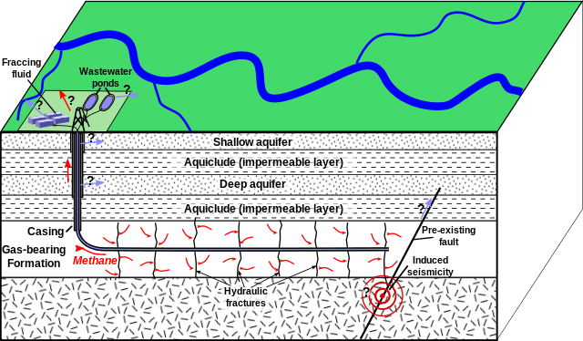
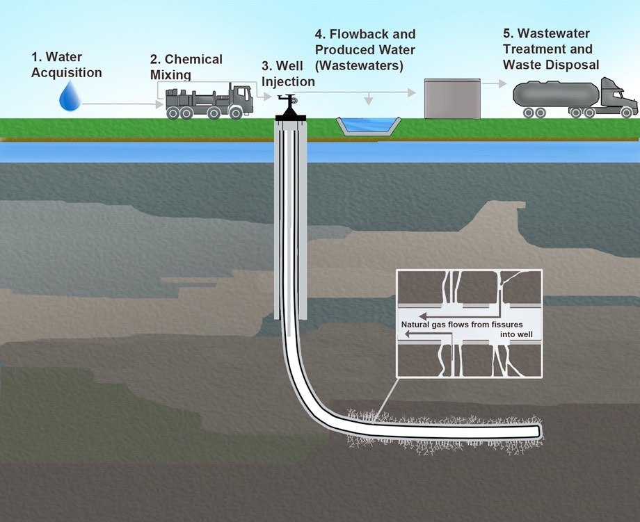
Tight oil and natural gas trapped in shale as well as natural gas in tight sands are extracted via hydraulic fracturing, informally referred to as “fracking”. This process uses explosives to create new fractures in these low-permeability rocks as well as increase the size, extent, and connectivity of existing fractures and then applies high-pressure fluid. First, a drill permeates the rock layers and then proceeds horizontally. Explosives then fracture rocks, freeing oil and natural gas. Finally, water, sand, and chemicals and injected, which flush out oil and natural gas (figure \(\PageIndex{i}\)).
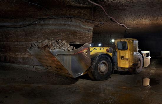
As mentioned previously, bitumen in tar sands can be extracted by injecting steam, or they may be mined for later processing. Tar sands can mined through strip mining or open-pit mining, a type of surface mining that involves forming a progressively deeper hole. The walls of the pit are as steep as can safely be managed. A steep wall means there is less waste overburden to remove and is an engineering balance between efficient mining and mass wasting. Oil shale is extracted by strip mining, creating subsurface mines, or open-pit mining. Oil shale can be burned directly like coal or baked in the presence of hydrogen to extract liquid petroleum (figure \(\PageIndex{j}\)).
Refining Crude Oil
The result of oil recovery is crude oil (petroleum), which contains many types of hydrocarbons as well as some unwanted substances such as sulfur, nitrogen, oxygen, dissolved metals, and water all mixed together. Unprocessed crude oil is therefore, not generally useful in industrial applications and must first be separated into different useable products (petrochemicals) at a refinery. Gasoline (petrol), diesel, tar, and asphalt are examples of petrochemicals.
Fractional distillation is the key process used in oil refineries to separate the components of crude oil. During fractional distillation, crude oil is heated and then allowed to cool. The heaviest compounds sink to the bottom as residues. Components of vaporized crude oil condense at different levels in the distillation column depending on their boiling points, which is primarily due to their molecular sizes. The heaviest compounds (condense near the bottom of the column, where the temperature is still high. Lighter compounds condense at cooler temperatures higher up in the column. Some compounds remain as gases at the top of the column (figure \(\PageIndex{k}\)).
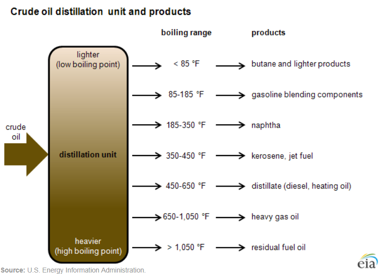
The video below explains the process of fractional distillation. The labeled distillation column at 3:00 shows heated crude oil (400 °C) separating into various petrochemicals. From bottom to top, they are bitumen (> 350 °C), diesel (250-350 °C), kerosene (160-250 °C), naphtha (70-160 °C), petrol (20-70 °C), and gas (< 20 °C).
Conversion is the chemical processing in which some of the fractions (produced from fractional distillation) are transformed in to other products. For example, a refinery can turn diesel fuel into gasoline depending on the demand for gasoline. Conversion can involve breaking larger hydrocarbon chains into smaller ones (cracking), combining smaller chains into larger ones (unification), or rearranging the molecules to created desired products (alteration).
Treatment is done to the fractions to remove impurities such as sulfur, nitrogen and water among others. Refineries also combine the various fractions (processed and unprocessed) into mixtures to make desired products. For example, different mixtures of hydrocarbon chains can create gasolines with different octane ratings, with and without additives, lubricating oils of various weights and grades (WD-40, 10W-40, 5W-30, etc.), heating oil, and many others. The products are stored onsite until they can be delivered to various markets such as gas stations, airports and chemical plants.
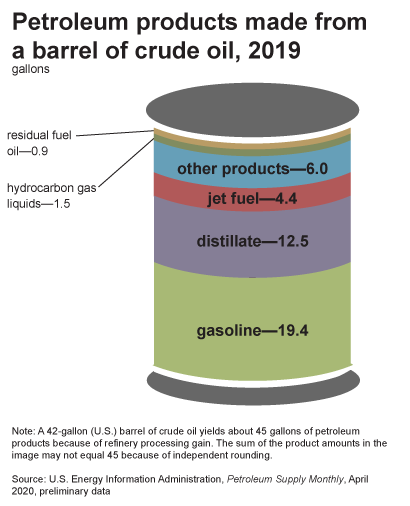
A 42 U.S. gallon barrel of crude oil yields about 45 gallons of petroleum products because of refinery processing gain (figure \(\PageIndex{l}\)). This increase in volume is similar to what happens to popcorn when it is popped. Gasoline makes up the largest fraction of all petroleum products obtained. Other products include diesel fuel and heating oil, jet fuel, petrochemical feedstocks (to manufacture plastics, synthetic rubber, or other chemicals), waxes, lubricating oils, and asphalt.
Transporting Oil and Natural Gas
After the refinery, the gasoline and other fuels created are ready to be distributed for use. A system of pipelines runs throughout the United States to transport oil and fuels from one location to another. There are pipelines that transport crude oil from the oil well to the refinery. At the refinery, there are additional pipelines that transport the finished product to various storage terminals where it can then be loaded onto trucks for delivery, such as to a gas station.
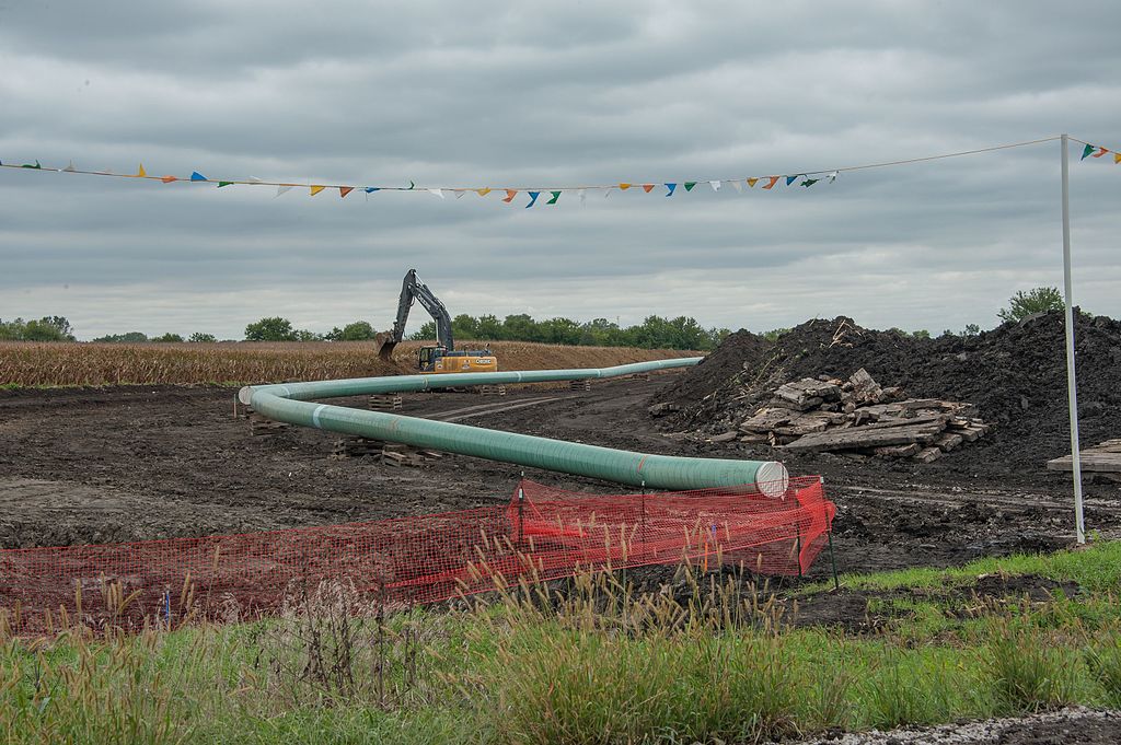
Once natural gas is produced from underground rock formations, it is sent by pipelines to storage facilities and then on to the end user. The United States has a vast pipeline network that transports gas to and from nearly any location in the lower 48 states. There are more than 210 natural gas pipeline systems, using more than 300,000 miles of interstate and intrastate transmission pipelines (figure \(\PageIndex{m}\)). Compressor stations that maintain pressure on the natural gas to keep it moving through the system. There are more than 400 underground natural gas storage facilities that can hold the gas until it is needed back in the system for delivery.
Generating Electricity from Oil or Natural Gas
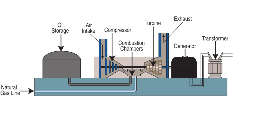
Natural gas is burned to produce electricity following the same general process used in a coal power plant (figure \(\PageIndex{n}\)). Oil is occasionally used to generate electricity as well.
Attributions
Modified by Melissa Ha from the following sources:
- Non-Renewable Energy Sources from Environmental Biology by Matthew R. Fisher (licensed under CC-BY)
- Fossil Fuels and Mining from An Introduction to Geology by Chris Johnson et al. (licensed under CC-BY-NC-SA)
- Chapter 4: Non-Renewable Energy from Introduction to Environmental Science: 2nd Edition (2018) Biological Sciences Open Textbooks by Zehnder, Caralyn; Manoylov, Kalina; Mutiti, Samuel; Mutiti, Christine; VandeVoort, Allison; and Bennett, Donna (licensed under CC-BY-NC-SA).
- Fossil Energy Study Guide: Natural Gas. 2014. U.S. Department of Energy. Accessed 01-12-2021.
- Fossil Energy Study Guide: Oil. 2013. U.S. Department of Energy. Accessed 01-12-2021.


