
iCn3D Tutorial: Asymmetric Unit, Unit cell, and Molecular Assemblies
- Page ID
- 128947
\( \newcommand{\vecs}[1]{\overset { \scriptstyle \rightharpoonup} {\mathbf{#1}} } \)
\( \newcommand{\vecd}[1]{\overset{-\!-\!\rightharpoonup}{\vphantom{a}\smash {#1}}} \)
\( \newcommand{\id}{\mathrm{id}}\) \( \newcommand{\Span}{\mathrm{span}}\)
( \newcommand{\kernel}{\mathrm{null}\,}\) \( \newcommand{\range}{\mathrm{range}\,}\)
\( \newcommand{\RealPart}{\mathrm{Re}}\) \( \newcommand{\ImaginaryPart}{\mathrm{Im}}\)
\( \newcommand{\Argument}{\mathrm{Arg}}\) \( \newcommand{\norm}[1]{\| #1 \|}\)
\( \newcommand{\inner}[2]{\langle #1, #2 \rangle}\)
\( \newcommand{\Span}{\mathrm{span}}\)
\( \newcommand{\id}{\mathrm{id}}\)
\( \newcommand{\Span}{\mathrm{span}}\)
\( \newcommand{\kernel}{\mathrm{null}\,}\)
\( \newcommand{\range}{\mathrm{range}\,}\)
\( \newcommand{\RealPart}{\mathrm{Re}}\)
\( \newcommand{\ImaginaryPart}{\mathrm{Im}}\)
\( \newcommand{\Argument}{\mathrm{Arg}}\)
\( \newcommand{\norm}[1]{\| #1 \|}\)
\( \newcommand{\inner}[2]{\langle #1, #2 \rangle}\)
\( \newcommand{\Span}{\mathrm{span}}\) \( \newcommand{\AA}{\unicode[.8,0]{x212B}}\)
\( \newcommand{\vectorA}[1]{\vec{#1}} % arrow\)
\( \newcommand{\vectorAt}[1]{\vec{\text{#1}}} % arrow\)
\( \newcommand{\vectorB}[1]{\overset { \scriptstyle \rightharpoonup} {\mathbf{#1}} } \)
\( \newcommand{\vectorC}[1]{\textbf{#1}} \)
\( \newcommand{\vectorD}[1]{\overrightarrow{#1}} \)
\( \newcommand{\vectorDt}[1]{\overrightarrow{\text{#1}}} \)
\( \newcommand{\vectE}[1]{\overset{-\!-\!\rightharpoonup}{\vphantom{a}\smash{\mathbf {#1}}}} \)
\( \newcommand{\vecs}[1]{\overset { \scriptstyle \rightharpoonup} {\mathbf{#1}} } \)
\( \newcommand{\vecd}[1]{\overset{-\!-\!\rightharpoonup}{\vphantom{a}\smash {#1}}} \)
Introduction
Structures available from the Protein Data Bank are just visualized data based on electron density maps. These are converted to 3D structures of connected atoms using computer processing and modeling to give atoms with XYZ coordinates. Often even the default PDB structures need more analyses to optimize our understanding of the structure and function of the molecules. To understand the vocabulary of X-ray crystal structures, we need to review some crystallography terms such as the unit cell, the asymmetric unit, and the biological assembly and how they are derived from X-ray crystal data.
The Asymmetric Unit and the Unit Cell
In introductory chemistry, you learned about several types of unit cells, simple cubic, body-centered cubic, and cubic closest or face-centered cubic. These are illustrated in the Figure 1 below which uses spheres to represent atoms, ions, or even molecules.

Figure 1: Simplest cubic unit cells.
One way to generate the unit cells is to add multiple layers of spheres to a bottom layer. For example, the simple cubic cell (layers AA) can be visualized with two layers with each sphere in layer 2 centered over the spheres in the bottom layer. For the body-centered cubic cell, the layers are staggered so that spheres in the second layer are located over holes in the first. The face-centered cubic cell (equivalent to cubic-closest packing) has layers ABC with spheres in layers B and C over holes in the layer beneath and above.
Now in your mind, propagate unit cells by translation to form other unit cells above, below, left, right, front, and back to generate a crystal lattice of unit cells. In doing so, how many spheres (representing atoms or ions) are in a single unit cell for each unit cell shown in the figure above? Remember that some of the spheres will be shared.
- Answer
-
- For the simple cubic cells, each corner sphere is shared by unit cells above, below, left, right, back, and front which in total give 8 unit cells. In the cell above, there are 8 spheres x 1/8 per each corner sphere, which gives 1 sphere per unit cell.
- For the body-centered cubic there would be 8x1/8 = 1 for each corner sphere and 1 for the enclosed sphere which is not shared by other unit cells. Hence there are 2 spheres/unit cell.
- For the face-centered cubic cells, there are 8x1/8 = 1 for each corner sphere, and since there is one sphere in each face, and each face is shared by only 2 adjacent cells, there are 6 faces x 1/2 = 3 face spheres. The sum is 4 spheres in the unit cell (note there is no sphere in the center).
The unit cells for the simple cubic packing can also be given as a single sphere in a cube (shown at the bottom of the simple cubic cell figure above. The entire crystal lattice could be built by this unit cell by translation in all directions.
For the same lattice of points, different types of unit cells can be drawn, as shown in the Figure below. Click on Figure 2 below to see a rotatable 3D model for a much better understanding of the figure.

Figure 2: A rotatable model showing different unit cells for the same lattice structure. Click to see the rotation. Aristov, M. M., Geng, H., Pavelic, A. & Berry, J. F. (2022). A new library of 3D models and problems for teaching crystallographic symmetry generated through Blender for use with 3D printers or Sketchfab. J. Appl. Cryst. 55, 172-179. https://journals.iucr.org/j/issues/2022/01/00/oc5017/. Creative Commons Attribution 3.0 un-ported license
Here is a link to a rotatable list of unit cells that include non-cubic examples.
a. What is the shape of the orange/gold unit cell in Figure 2 above?
b. What is the name of the red, green, and blue unit cells in Figure 2 above?
- Answer
-
a. monoclinic (1 axis perpendicular, others inclined, each side different
b. orthorhombic base-centered
When we think about the crystal structure of proteins, it gets more complicated since the single repeating unit is not just a sphere but a structure with primary, secondary, tertiary, and quaternary structures. To understand this, we have to introduce a few more terms, including the asymmetric unit and the biological assembly. The unit cell and the crystal lattice are pretty straight forward to understand. The biological assembly is more complicated.
The Protein Data Bank has a great description of the asymmetric unit, the unit cell, and the entire crystal lattice. The asymmetric unit is the "smallest portion of a crystal structure to which symmetry operations can be applied to generate the complete unit cell. The unit cell is the smallest part of a crystal lattice that repeats to create the entire crystal lattice to fill out space. For the simple cubic cell, the asymmetric unit is the sphere. The common symmetry operations relevant to us are translations, rotations, and combinations of them. The generation of a unit cell and an entire crystal from a 2D asymmetric unit, an arrow analogous to a beta-strand, is illustrated in Figure 3 below.

Figure 3: Generation of a unit cell and an entire crystal from the asymmetric unit. Introduction to Biological Assemblies and the PDB Archive. Shuchismita Dutta, Rachel Kramer Green, and Catherine L. Lawson. https://pdb101.rcsb.org/learn/guide-...cal-assemblies
Could you generate the unit cell by just translating (moving along an axis) the green arrow? If not, what is required?
- Answer
-
The asymmetric unit is one arrow pointed up. It can be rotated 1800 around the black vertical axis to produce the purple stand. Together these make up the unit cell. Now pack these unit cells together (making them by duplication and translation) and you get the entire crystal lattice. You couldn't just replicate the green arrow and pack it to generate the lattice.
Figure 4 shows another more realistic example using a protein, where the unit cell determined in the x-ray analysis is a homotetramer (homo 4-mer).

Figure 4: The unit cell consisting of a homotetramer (left) and a 2-unit cell "lattice" generated from it (right) are shown. Jagodzinski et al.BMC Bioinformatics 2013, 14(Suppl 18):S2. http://www.biomedcentral.com/1471-2105/14/S18/S2. Creative Commons Attribution 2.0 Generic
a. What is the asymmetric unit in the unit cell on the left? What symmetry operations could be used to generate the actual unit cell?
b. What symmetry operations were used to generate the 2-cell lattice? Are there any protein-protein interactions seen in the unit cell (left) or the 2-cell lattice (right)?
- Answer
-
a. The asymmetric unit is one monomer. The other monomers could be generated by combinations of symmetry operations (translations and rotations) to form the monomers in the unit cell shown in the left panel.
b. Simple translation is used to create the right-hand unit cell. No obvious protein-protein interactions are seen in the left unit cell but they are present in the 2-unit cell figure.
Biological Assembly
Structure mediates function, and we are interested in not just the structure of the asymmetric unit or unit cell, but the structure of the biological functional unit, which might be a monomer or homo- or hetero dimer, trimer, tetramer or n-mer. This "presumed" functional unit is called the Biological Assembly. This is more complicated to understand and is subject to interpretation. The biological assembly is best determined both by experimentation and crystallography.
To illustrate a bit of the complexity, take an "apparent" dimer. Is there experimental evidence that a dimer is the active form of a protein in solution or a membrane? Could a dimer determined by X-ray crystallography be an artifact of the very high concentration required to form crystals from a protein in solution? A monomer (M) could form a weak, but not a biologically-relevant association with itself to form a dimer (D), as illustrated by this simple chemical equation: M + M ↔ D. An active monomer then could be forced (consider Le Chatelier's Principle) into a "nonbiological" dimer simply by the high concentration required for protein crystallization.
In X-ray crystallography, the biological assembly could be predicted computationally by conducting a series of symmetry operations on the asymmetric unit or by using just some of the coordinates. This could result in a biological assembly that is part, one, or many copies of the asymmetric unit. Yet experimental data might show that the protein is active as a monomer in a solution. A part of the actual PDB file termed REMARK 350 shows if the finalized biological assembly is experimental (provided by the authors) or determined by the software. The Protein Interfaces, Surfaces and Assemblies Server (PISA) is often used to calculate the biological assembly of possible quaternary state. Programs like this use algorithms that calculate buried surface areas (between monomers), which if high would stabilize dimers and multimers, and free energies of interactions between monomers. Sometimes there are contacts in the crystal that are not found in the biological assembly so they are likely artifacts of crystallization. These are called crystal contacts. The program tries to differentiate these from interchain contacts that have been preserved in evolution and hence likely to be "real", not artifactual contacts, that promote quaternary structure.
Authors might not even know if experimental evidence shows that multimers exist. So in a way, the biological assembly is a best guess for the main functional unit of the protein. In addition, changes in solvent conditions, ligand binding, or post-translational modifications could promote changes in the quaternary state of the protein, which further complicates the concrete prediction of the biological assembly. Most simply, if it is determined only by software and not experimentation (as indicated in REMARK 350), the proposed biological assembly should be considered a guess at best.
Structures determined by X-ray crystallography are usually, but not always, deposited as files containing the coordinates for one asymmetric unit. The entire structure then has to be generated from it. Depending on the crystallization conditions, the packing of the proteins in the crystal, and the computational analyses used, the biological assemblies can be different, much as multiple different types of unit cells can be drawn through a lattice of points as illustrated in Figure X above).
In summary, we should consider the proposed biological assemblies with caution unless they are supported by experimental data. Since they are so important (since structure mediates function), let's look at many examples of structures and view their asymmetric units and biological assemblies.
Examples
Dihydrofolate Reductase
The enzyme dihydrofolate reductase (DHFR) is active as a monomer in some species (mesophilic - EcDHFR, pdb 1RX2, thermophilic - BsDHFR, pdb 1RX2, and cold-adapted - MpDHFR, pdb 1D1G) and a dimer in another (hyperthermophilic - TmDHFR, pdb 2ZZA).
Toggle between the biological assembly and the asymmetric unit in the top left window of the PDB page for the enzymes  to see the biological assemblies and the asymmetric unit, which are shown in Table 1 below for a monomeric and dimeric form of the enzyme.
| Enzyme | Asymmetric Unit | Biological Assembly |
| mesophilic - EcDHFR, pdb 1RX2 |  |
 |
| hyperthermophilic - TmDHFR, pdb 2ZZA |  |
The PDB shows this as having 2 different biological assemblies that are both monomeric |


Table 1: DHFR asymmetric units and biological assemblies
For the known dimeric 2ZZA, the asymmetric unit is the dimer, but instead of the biological assembly being the dimer, there are two different monomeric biological assemblies, which in this case are both represented in the asymmetric unit.
Hemoglobin
The complexity of asymmetric units and biological assemblies calculated from different hemoglobin structures is illustrated in Table 2 below. These examples are derived from the wonderful article in the PDB 101 - Introduction to Biological Assemblies and the PDB Archive. (Dutta et al., ibid). Note that the table is organized from top to bottom
|
Asymmetric unit = Biological Assembly |
Asymmetric unit = 1/2 biological assembly |
Asymmetric unit = 2 biological assemblies |
|---|---|---|
|
Asymmetric Unit = α2β2
|
Asymmetric Unit = αβ
|
Asymmetric Unit = (α2β2)2
In this case, there are 2 different biological (functional) assemblies in the asymmetric unit |
|
Biological Assembly = α2β2 = full Hb click image to view iCn3D
In this case, the asymmetric unit is the same as the biological assemble |
Biological Assembly - α2β2 click image to view iCn3D
symmetry operation = 1800 rotation (2-fold axis) (360/180 = 2) In this case there are 2 asymmetric units in the biological assembly |
Biological Assembly 1 and 2 each = α2β2 click images to view iCn3D
In this case, there are 2 biological assemblies |
|
Pymol "Unit Cell" but better termed Asymmetric Unit
|
Pymol Asymmetric Unit
This is not the unit cell since it can not simply be translated in the XYZ directions to form the lattice. The unit cell could be generated from this by symmetry operations (translation and rotations) |
Pymol Asymmetric Unit
|

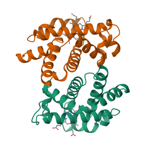


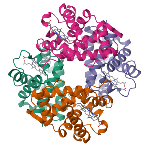


Table 2: Hemoglobin - Asymmetric Units and Biological Assemblies
Note again that where there are two biological assemblies, they are sometimes combined to form the asymmetric unit!
Click on the images in the biological assembly row to get iCn3D models for the assembly. The iCn3D model was made by opening iCn3D and then choosing: File, Retrieve by ID, RCSB mmCIF ID instead of the usual mmDB or PDB files. The CIF files often used in displaying crystallographic information.
To toogle between the biological assembly (default) and asymmetric unit, choose Analysis, Assembly, Asymmetric Unit (and repeat).
a. What do you see?
b. You can also toggle between the asymmetric unit and the biological assembly by going to the PDB page for the structures above and clicking the arrow (circled red below) in the upper left of the pdb page. Are the results the same as the images above and in iCn3D?
- Answer
-
All of the asymmetric unit iCn3D structures matched those in the table above or viewing the asymmetric unit/biological assembly at the PDB.
Citrate Synthase (1CTS)
Use the following instructions to model the asymmetric unit and molecular assembly for 1CTS in iCn3D
- File, Retrieve by ID, RCSB mmCIF ID
- Style, Background, Transparent
- Analysis, Assembly, Asymmetric Unit (and repeat)
Take screen snips of the AU and the Biological Assembly and place in the table below
| Asymmetric Unit | Biological Assembly |
| Paste short link here: File, Share Link, Short Link: | |
- Answer
-
Here they are. Note: the two chains in the biological assembly are both colored red since loaded mmCIF files can't be colored by chain in iCn3D
Asymmetric Unit Biological Assembly 

short link: https://structure.ncbi.nlm.nih.gov/i...XvueVPW3QQeUMA
Pymol is a widely used biomolecular visualization program. When using the program to load 1CTS, only the asymmetric unit, the monomer, is loaded, even though the dimer is the function unit (or biological assembly). There are two ways to display the dimer. One is to select File, Get PDB and then load the assembly as shown in Figure 5 below.

Figure 5: Loading a biological assembly in Pymol
Here is a second way.
The actual dimer can also be created in Pymol by generating a "symmetry mate" for the monomer. This can be done by following these commands within the Pymol GUI as shown below. This section is derived from a YouTube tutorial by Kristen Procko.

Figure: Creating symmetry mates based on YouTube tutorial by Kristen Procko.
Many will be generated based on a series of symmetry operations. Only 1 is optimal (last one). The A and B subunits bind in a complementary fashion without regions of the original asymmetric unit "floating in space".
Take a snip of the modeled dimer.
- Answer
-
Here is the packed dimer made in Pymol using this procedure and a free academic version can be downloaded. The subunits are colored differently.

Figure: Dimer of citrate synthase created using Pymol symmetry mates (based on YouTube tutorial by Kristen Procko)
Fibrinogen-like recognition domain of FIBCD (6ZR4) of the fibrinogen C domain-containing protein 1 (FIBCD1) membrane protein 6ZR4
Now we will use another protein, the extracellular fibrinogen-like recognition domain of FIBCD (6ZR4) of the fibrinogen C domain-containing protein 1 (FIBCD1) membrane protein. The protein is a pathogen-associated molecular pattern (PAMP) receptor in the innate immune system that recognizes chitin and its derivatives.
Its crystallographic properties are somewhat analogous to 1hv4 above in that it has two biological assemblies, but there are other significant differences. The two are compared in Table 3 below.
| PDB 1hv4 (Asymmetric unit = 2 biological assemblies) | PDB 6ZR4 (Asymmetric unit = 2 biological assemblies) |
|---|---|
|
Asymmetric Unit = (α2β2)2
In this case, there are 2 different biological (functional) assemblies in the asymmetric unit |
In this case, there are 2 different chains, A and B (same sequence, one glycosylated (A) in the asymmetric unit |
|
Biological Assembly 1 and 2 each = α2β2 click images to view iCn3D
In this case, there are 2 biological assemblies |
Biological Assembly 1 = A4 (with glycans); Biological Assembly 2 = B4
In this case, there are 2 biological assemblies |
|
Pymol Asymmetric Unit
|
Pymol Asymmetric Unit
|


Table 3: Asymmetric Units and Biological Assemblies for 1HV4 (hemoglobin) and 6ZR4 (FIBCD)
Let's use iCn3D to load different file types for 6ZR4 and make snips of the asymmetric units and biological assemblies. The A subunit with the glycan will be shown in magenta and the B subunit in blue.
Add the snips to this table
| File, Retrieve by ID, ... compare these types | asymmetric unit | molecular assembly |
| RCSB PDB | ||
| NCBI mmDB ID | ||
| mmCIF |
- Answer
-
Here they are.
File, Retrieve by ID, asymmetric unit molecular assembly RCSB PDB 

NCBI mmDB ID 
mmCIF 

The asymmetric unit structure not in accord with the others is the MMDB file which shows only the A chains with the glycan but no B chain.
If you look at the magenta A subunits with the trisaccharide, the glycan never appears to interact with any of the subunits, yet data shows that it does interact with the B subunit.
Given these results, we will use the PDB file for further processing.
Create a FIBCD (6ZR4) AB dimer using Pymol
It's easy to generate in a black-box fashion symmetry mates for the fibrinogen-like recognition domain of FIBCD (6ZR4) of the fibrinogen C domain-containing protein 1 (FIBCD1). Follow these simple instructions. First, get the file by selecting File, Get PDB. Then follow Figure 6 below.
Figure 6: Creating symmetry mates in Pymol
Now the symmetry mates will include some with AA dimers and BB dimers but also some with AB dimers in which there the trisaccharide in the A monomer is bound to the B subunit.
Model the optimal symmetry mates of the AB dimer in Pymol and find the optimal one that shows A:B interactions and B interacting with the trisaccharide on the A chain. Hide the other chains and take a screen snip.
- Answer
-
Here it is. The A chain (magenta) has the N340-linked trisaccharide shown in space fill interacting with the B chain (cyan).

Using iCn3D to create an AB dimer with trisaccharide:protein interactions
iCn3D can be used to carry out symmetry operations on the PDB file to show an alpha-beta dimer. Follow the detailed instructions below and paste your results in the appropriate place below. This procedure was made by Jiyao Wang. It involves rotation matrices to make rotations around the XYZ axes.
Here is a bit of a review of matrices before we start.
For rotation of points in just the xy axes through a counterclockwise angle θ, the matrix equation is used:
\begin{equation}
R=\left[\begin{array}{cc}
\cos \theta & -\sin \theta \\
\sin \theta & \cos \theta
\end{array}\right]
\end{equation}
For 90°, 180°, and 270° counter-clockwise rotations, the matrices become.
\begin{equation}
\left[\begin{array}{cc}
0 & -1 \\
1 & 0
\end{array}\right], \quad\left[\begin{array}{cc}
-1 & 0 \\
0 & -1
\end{array}\right], \quad\left[\begin{array}{cc}
0 & 1 \\
-1 & 0
\end{array}\right]
\end{equation}
Remember that:
| function | 900 | 1800 | 2700 |
| sin | 1 | 0 | -1 |
| cos | 0 | -1 | 0 |
In the biological matrices (BIOMT) below, the PDB files can be translated by rotation around 3 possible axes, XYZ, so you'll see lots of 0, 1, and -1. Hopefully, you might now have at least a superficial sense of where they come from.
1. Open https://www.ncbi.nlm.nih.gov/Structure/icn3d/full.html?pdbid=6ZR4 and show the electron density map using Style, Electron Density,2Fo-Fc Map. Then press “Ctrl” plus “Shift” plus “i” to show the console. It shows the following information:
header: {"xStart":-17,"yStart":15,"zStart":-36,"xExtent":111,"yExtent":143,"zExtent":106,"xRate":160,"yRate":160,"zRate":64,"xlen":118.3375,"ylen":118.3375,"zlen":44.087500000000006,"alpha":90,"beta":90,"gamma":90}
xlen, ylen, and zlen are the lengths of the unit cell, and alpha, beta, and gamma are the angles of the unit cell.
2. Open the actual PDB file of 6ZR4 using a text editor to see the relevant REMARK 350 section and to get the rotational matrix. Use the yellow-highlighted matrix for the data needed in the next step.
REMARK 350 BIOMT1 1 1.000000 0.000000 0.000000 0.00000
REMARK 350 BIOMT2 1 0.000000 1.000000 0.000000 0.00000
REMARK 350 BIOMT3 1 0.000000 0.000000 1.000000 0.00000
REMARK 350 APPLY THE FOLLOWING TO CHAINS: B
REMARK 350 BIOMT1 2 -1.000000 0.000000 0.000000 118.34900
REMARK 350 BIOMT2 2 0.000000 -1.000000 0.000000 118.34900
REMARK 350 BIOMT3 2 0.000000 0.000000 1.000000 0.00000
REMARK 350 APPLY THE FOLLOWING TO CHAINS: B
REMARK 350 BIOMT1 3 0.000000 -1.000000 0.000000 118.34900
REMARK 350 BIOMT2 3 1.000000 0.000000 0.000000 0.00000
REMARK 350 BIOMT3 3 0.000000 0.000000 1.000000 0.00000
REMARK 350 APPLY THE FOLLOWING TO CHAINS: B
REMARK 350 BIOMT1 4 0.000000 1.000000 0.000000 0.00000
REMARK 350 BIOMT2 4 -1.000000 0.000000 0.000000 118.34900
REMARK 350 BIOMT3 4 0.000000 0.000000 1.000000 0.00000
- Open https://www.ncbi.nlm.nih.gov/Structure/icn3d/full.html?pdbid=6ZR4 and just show the asymmetric unit using “Analysis > Assembly > Asymmetric Unit”. (Note: this is the PDB file, not the MMDB or mmCIF files).
- Select chain B (6ZR4_B)after clicking Analysis, Defined Sets.
- Click View, > Rotate with Matrix and input the data from the three lines of matrix above as shown below and click Rotate with Matrix. A table will appear
Use the three yellow-highlighted lines to fill out the corresponding positions of the matrix as shown in the figure below.
REMARK 350 BIOMT2 4 -1.000000 (1) 0.000000 (5) 0.000000 (9) 118.34900 (13)
REMARK 350 BIOMT3 4 0.000000 (2) 0.000000 (6) 1.000000 (10) 0.00000 (14)
The last line of the matrix (positions 3, 7, 11, 15) should be the default 0,0,0,1.
6. Next click View, Translate XYZ and then input X: 0, Y: 0, Z: -44.09. Then click Translate.
7. Style, Background, Transparent
8. (you can save a link to this state by File, Share Link, Lifetime Short URL)
To manipulate the processed file you need to save the B file and then the A+C file separately as PDB files.
9. While the B chain is selected, click File, Save File, PDB to save the transformed PDB file. Open the PDB file in a text editor (like Notepad for the PC) to remove everything except the coordinates in the file. Name the file as “chain B.pdb”.
10. While A chain and the glycans are selected, click File, Save File, PDB to save the transformed PDB file.
9. Using a text editor, remove everything except the coordinates in the PDB. Name the file as “chain A and glycan.pdb”.
10. File, Open, PDB Appendable, and then open both new files to display the A:B complex with the glycan bound to the B chain.
11. File, Save File, PDB, and give the combined file a single name.
Now let's display the file.
Use iCn3D to display the concatenated file.
- File, Open File, PDB and choose the concatenated PDB file (if not already opened)
- Analysis, Seq. and Annotations, and then in right hand window choose the details tab
- Click Chem Struct_C, which is the trisaccharide
- Select, Save Selection, and name it trisacch
- Style, Chemical, Sphere
- With the mouse, alt-click N340 in the magenta chain close to the trisaccharide
- Select, Save Selection, and name it D340
- Style, Side Chains, Stick
- Color Atom
- Analysis, Label, Per residue and label
- Analysis, Label Scale, 3
- Style, Background, Transparent
Snip an image of the dimer below.
- Answer
-
Here it is. The A chain is shown in magenta and is N-linked to the trisaccharide (spacefill). The B chain (cyan) is shown interacting with the trisaccharide.
