
19.2: ATP Synthesis
- Page ID
- 15040


Search Fundamentals of Biochemistry
Introduction
ATP synthase, also called F1FoATPase, is a rotary motor enzyme. This enzyme is found in the inner membrane of mitochondria, the analogous thylakoid membranes of chloroplasts, and the cell membrane of bacteria. The enzyme consists of two parts, the membrane-bound Fo which is a proton translocator, and the F1 part which has catalytic (ATP synthesis or hydrolysis activity. The Fo part can be considered to be a rotary electrical motor powered by proton flow, while the F1 part acts as a rotary chemical motor powered (in reverse) by ATP hydrolysis. The Fo part is named since it is sensitive to oligomycin (note that it should theoretically be read as Fo and not Fzero). The F1 part is named since it was eluted from a column chromatography column in Fraction 1.
The elucidation of its structure and mechanism by many but especially by Paul D. Boyer and John E. Walker, was a major feat of scientific study. They, along with Jen Skou, who studied the mechanism of the analogous Na/K ATPase, were awarded the Nobel prize for their work.
Let's start with the known structure of this complicated membrane-bound rotary enzyme and then work towards an understanding of how it works. The structure of the bovine F1FoATPase is shown in Figure \(\PageIndex{1}\).

Figure \(\PageIndex{1}\): Bovine F1FoATPase.
In the previous section, we discussed how oxidative electron transport in the mitochondria is accompanied by proton transport against a concentration gradient from the matrix through the inner member to the intermembrane space. The synthesis of ATP from ADP and P1 is endergonic and requires an energy source. That energy source is provided by the thermodynamically favored collapse of the pH gradient across the mitochondrial inner membrane. Protons flow through the Fo membrane spanning C helices from the intermembrane space (not shown in Figure 1) to the matrix. This powers the synthesis of ATP from ADP and Pi by the F1 part of the enzyme in the matrix lumen.
Figure \(\PageIndex{2}\) shows an interactive iCn3D model of the entire bovine mitochondrial ATP synthase (5ARA). The subunits are shown in the same color as Figure 1 above.
.png?revision=1&size=bestfit&width=257&height=345)
 Figure \(\PageIndex{2}\): Bovine mitochondrial ATP synthase (5ARA). (Copyright; author via source). Click the image for a popup or use this external link: https://structure.ncbi.nlm.nih.gov/i...3YUBWrX91nnua9
The enzyme is reversible. If protons flow down a concentration gradient through Fo, ATP is synthesized by F1. Alternatively, ATP hydrolysis by F1 leads to the transport of protons through Fo and against a concentration gradient. Isolated F1 can only break down ATP, and not synthesize it.
We called this structure a rotary enzyme, so what rotates? A rotary "axle" protein complex comprised of the γ, ε, and δ subunits (some also describe the γ, ε, and δ subunits as part of F1) rotates. Its interactions with the multimeric complex of c alpha helices (shown in purple in the figures above) in the main Fo complex causes the "c-ring complex" complex in Fo to rotate as well. The F1 part does not rotate because of the conformational stability of the β subunit and the connection to the long alpha helices of the D and B1 proteins, which comprise the "stator (the stationary) part of an electric motor", which keeps F1 stationary.
Hence the enzyme does truly act like an electric motor, whose components are shown in Figure \(\PageIndex{3}\).
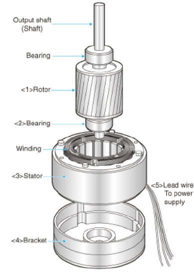
Figure \(\PageIndex{3}\): Electric motor with rotor, shaft, and stator. http://www.cdmmotor.com/en/article-22982-28485.html
Now let's look at the mechanisms and the evidence for them for each part of this remarkable enzyme.
F1
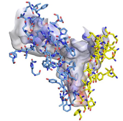
The F1 unit (with a quaternary structure of a3β3 forming a hexagonal ringed structure with a central cavity, occupied by a gamma subunit)is about 80 angstroms from the Fo subunit and both are connected to the rod-shaped γ subunit which spans the center of the a3β3 ring. Energy transduction (necessary to capture the negative free energy change associated with the collapse of the proton gradient to drive the positive free energy change for ATP synthesis) occurs between the two subunits.
Figure \(\PageIndex{4}\) shows a top view of the α (red) and β (green) subunits in the a3β3 F1 complex
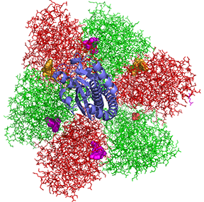
Figure \(\PageIndex{4}\): Top view of the α (red) and β (green) subunits in the a3β3
The γ subunit is shown coming out of the plane of the ring. ATP is shown in gold spheres, ADP in purple, and the smaller SO42- (from a crystallizing agent) is shown in CPK spheres. They are sandwiched between the a and β subunits.
Boyer, in the absence of the complete structure of the F1Fo ATP synthase, was able to deduce from experimental evidence that the a3β3 complex, which can be viewed as three aβ dimers (with catalysis occurring between subunits of individual dimers where ATP and ADP bind), have three different, interconvertible conformation defined as a Loose (L), Open (O) and Tight (T) states, with names describing the strength of substrate binding in each dimer.
- O - open state with very low affinity for substrates and has no catalytic activity;
- L - loose state with low affinity for substrates and also no catalytic activity;
- T - tight state with high affinity for substrates and with catalytic activity.
The three states rotate not physically with respect to some central axis but conformationally, depending on their interaction with the γ subunit which binds perpendicularly in the central junction of the a3β3 ring. Changes in the orientation of the central γ subunit due to its rotation with respect to the a3β3 ring cause the conformation of the O, L, and T states to change in situ with the orientation of the rotating γ subunit
The conversion of the LOT conformations, their binding of substrates (ADP and Pi), the conversion of bound ADP and Pi, and the release of the product (ATP) proposed by Boyer are shown in Figure \(\PageIndex{5}\).
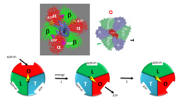
Figure \(\PageIndex{5}\): Boyer's three-state conformational model (L-O-T) for ATP synthesis
The collapse of the proton gradient (i.e. the proton-motive force) causes the γ subunit to rotate like a crankshaft relative to the F1 subunit, forcing the β subunit to change conformation from the T to the O (releasing ATP) and then to the L (binding ADP and Pi) states. The γ subunit does not appear to undergo any significant conformational change on ATP hydrolysis as evidenced by tritium exchange studies of amide protons.
To prove that the γ subunit rotates, you'd have to observe a single molecule. Since the γ subunit was too small to visually discern its rotation, Noji et al covalently attached a fluorescein-labeled actin filament to the γ subunit (near where Fo would bind). The whole F1 molecule was fixed to a glass slip through a His-tag such that the a3β3 ring was effectively immobilized. The γ subunit was free to rotate, which could be detected by observing the fluorescence under a fluorescent microscope from the attached actin filament. This experiment and the outcomes are described in Figure \(\PageIndex{6}\).

Figure \(\PageIndex{6}\): The direct observation of the γ rotation in the F1 motor. Noji and Yoshida. JBC (2001) DOI:https://doi.org/10.1074/jbc.R000021200. Creative Commons Attribution (CC BY 4.0)
Panel A shows the experimental system for the observation of the γ rotation using an optical microscope. The F1 motor tagged with 10 His residues at the N terminus of the β subunit was immobilized upside down on a coverslip coated with nickel-nitrilotriacetic acid (Ni-NTA). An actin filament (green) labeled with fluorescent dyes and biotins was attached to the biotinylated γ subunit (gray) through streptavidin (blue).
Panel B shows the rotary movement of an actin filament observed from the bottom, the membrane side, with an epifluorescent microscope. Length from the axis to tip, 2.6 μm; rotary rate, 0.5 revolutions per s; the time interval between images, 133 ms.
The actin filament rotated only in the presence of ATP. It rotated only counterclockwise, indicating that the motion was not random, but a specific motion of the γ subunit. At extremely low concentrations of ATP, rotation occurred only in 120o increments, implying one step per molecule of ATP hydrolyzed. (Remember the β subunits are separated by 120o ). As the rotation occurs, there is viscous resistance to the movement of the actin filament. He calculated that for a single 120o step caused by hydrolysis of a single ATP molecule, the amount of work was 80 piconewton which is about the free energy of hydrolysis of a single ATP molecule.
Later experiments in which a colloidal gold nanoparticle (40 nm diameter, with less frictional resistance to movement) was used instead of an actin filament showed the same result. At low [ATP], the motor rotates in 120o steps. At high [ATP], the rotation rate becomes continuous and saturates (with Michaelis/Menten kinetics) at 130 revolutions per second.
Other experiments using immobilized ATPase and magnetic tweezers have addressed the timing of substrate binding and product release when the enzyme is run in reverse (ATP hydrolysis). On rotation of the γ subunit, the three binding sites change properties. In hydrolysis, ATP binds to the open site and helps promote the 120-degree rotation. In the next step, ATP is hydrolyzed. In the final step, products dissociate. Pi dissociation occurs last from the third site. Hence each of the 3 beta-binding sites has different roles. One binds the substrate, one performs catalysis and third releases products. Assuming the synthesis pathway is the reverse of the ATPase reaction, the final release of Pi in ATP cleavage predicts that Pi binds first in the synthetic direction. This would preclude the binding of ATP next which is critical since its concentration during synthesis can be 10x higher than that of ADP. As Pi is bound first, only ADP, not ATP can bind next.
The γ subunit rotation plays a "catalytic" role as its rotation induces cyclic conformational changes in the beta subunit of the synthase. Can ATP synthesis occur without the gamma subunit by a mechanism that involves a less proficient, but a concerted set of cyclic changes in beta subunit conformation? It can. Uchihashi et al have used high-speed atomic force microscopy (AFM) to study the a3β3 ring from the F1 subunit without the gamma subunit. They found that upon ATP hydrolysis, the beta subunits underwent conformational changes in the same counterclockwise rotary direction as when the gamma subunit was present. This is illustrated in Figure \(\PageIndex{7}\).
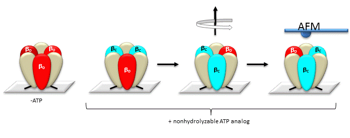
Figure \(\PageIndex{7}\): AFM Study of Conformational Changes in F1 "gammaless" subunit
These experiments conclusively show that the F1 subunit is effectively a rotary motor with the gamma subunit acting as a rotor in the stationary hexagon ring composed of the 3 pairs of alpha/beta subunits which acts as the stator (stationary part of an electric rotary motor).
The actual amino acids involved in the mechanism of ATP synthesis/hydrolysis are still not clearly defined but Glu 190 on the beta subunit acts as a general base. Figure \(\PageIndex{8}\) shows bound ADP and the proximity of Glu 188. Ala 158 is thought to move towards the active site after a conformational change, with the nonpolar methyl side chain displacing an adjacent water molecule which could leave as a product of ATP synthesis.
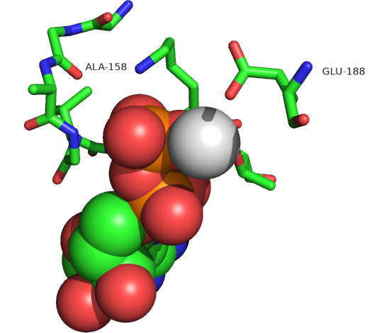
Figure \(\PageIndex{8}\): Active site residues for the synthesis of ATP. ADP is shown in spacefill, and CPK colors. Mg2+ is shown as a gray sphere (1E79).
Fo and Proton Transfer
The mechanism by which the proton gradient drives ATP synthesis involves a complex coupling of the Fo and F1 subunits. Proton translocation occurs through the interface of the inner mitochondrial (or cell membrane of bacteria) membrane proteins C1 and A (or beta), whose structures from the bovine enzyme are shown again in Figure \(\PageIndex{8}\).
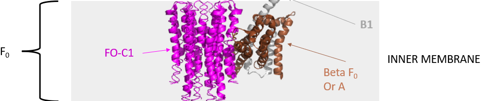
Figure \(\PageIndex{8}\): Inner membrane proteins C1 and A (or beta)
For protons to translocate through the membrane, there must be an aqueous channel on the matrix side and the lumenal side (bounded by the inner and outer mitochondrial membranes). So we have two understand two features:
- how the rotary axle part of the complex interacts with the C1 hexameric ring, causing the ring to rotate in the membrane.
- The nature of the water channels and the pathway for proton translocation.
The number of c monomers in the c-ring can vary between 8-17. For example, the bovine ATP synthase shown in Figures 1 and 2 has 8 c-monomers. Each has a critical proton donor and acceptor located near the a or beta-Fo chain. In the bovine case, it is glutamate 58. (The side chains in the bovine structure presented in Figure 2 do not show since they were not resolved in the cryoEM structure.) In E. Coli, which we will explore further below, it is aspartate 61. In yeast, it is at position 59. They are positioned near the center of the membrane helices. Mutations in these residues cause significant decreases in enzyme activity. An E56Q mutation in some bacilli species prevents proton pumping and ATP synthesis. Another key charged group, arginine, in the a or beta Fo protein is also key.
Figure \(\PageIndex{9}\) shows an interactive iCn3D model of the E. Coli A1-C12 subcomplex of F1FO ATP Synthase (1C17).
.png?revision=1&size=bestfit&width=569&height=366)
Figure \(\PageIndex{9}\): E. Coli A1-C12 Subcomplex OF F1FO ATP Synthase (1C17). (Copyright; author via source). Click the image for a popup or use this external link: https://structure.ncbi.nlm.nih.gov/i...sfRJBHEBiC5sy9
The key aspartate 61 (sticks and labeled) in each C ring subunit (red) and the proximity of two of the aspartate 61s to arginine 210 in the A subunit (brown) are evident.
Two classic inhibitors (structures shown below) of ATP synthase interact with the Fo subunit. One, oligomycin A, binds between the a and c subunits and blocks proton transport activity of the Fo subunit. The O protein at the top of the F1 complex is also called the Oligomycin-sensitivity-conferring protein (OSCP), even though oligomycin does not bind there. The soluble F1 by itself is not sensitive to oligomycin, but when it's linked to Fo in part through the O or OSCP peripheral stalk protein, it becomes sensitive to oligomycin.
Another inhibitor, dicyclohexylcarbodiimide reacts with a protonated Asp 61 in c subunits of Fo. It does so even at pH 8.0 which indicates that the pKa of the Asp 61 is much higher than usual. This might occur if the Asp is in a very hydrophobic environment. The modification of one Asp 61 in only one c subunit is necessary to stop Fo activity. The protonated carboxyl group donates a proton to a nitrogen atom in DCCD, which then reacts with the deprotonated Asp to form an O-acyl isourea derivative. Figure \(\PageIndex{10}\) shows the structures of oligomycin A and DCCD, inhibitors of proton transport by Fo.

Figure \(\PageIndex{10}\): structures of oligomycin A and DCCD
Figure \(\PageIndex{11}\) shows an interactive iCn3D model of the F1FoATPase c10 ring with bound oligomycin (4F4S)
.png?revision=1&size=bestfit&width=132&height=292)
Figure \(\PageIndex{11}\): E. Coli A1-C12 Subcomplex OF F1FO ATP Synthase (1C17). (Copyright; author via source). Click the image for a popup or use this external link: https://structure.ncbi.nlm.nih.gov/i...pJw1pFr8jTPmK8
Only two of the c-subunits are shown interacting with one oligomycin. The actual complex has 10 c-subunits and 8 oligomycins bound. The oligomycin is shown in spacefill with CPK colors. The two c-subunits are shown in gray. The side chains from the two c-subunits interacting with oligomycin are shown as CPK-colored sticks. They are conserved between humans and yeast. Note the single H bond between the critical Glu 59 and oligomycin. The green colors indicate hydrophobic parts of the c-subunits which interact with the mostly nonpolar parts of the antibiotic.
How do these key Asp or Glu side chains participate in proton translocation across the membrane and c-ring rotation and how do they access the matrix and lumenal water channels?
We can start to understand the answer to these question by examining the structure of the c-ring and its interaction with the a-chain from Bacillus PS3 ATP synthase, as shown in Figure \(\PageIndex{12}\), which show the key Glu59 residues in each of the c subunits of the 10-mer ring along with Arg 176 and two other glutamates (Glu 223 and Glu 162) in the A ring.

Figure \(\PageIndex{12}\): Schematic picture of the a-subunit and c-ring of Fo. Mitome et al. (2022). eLife 11:e69096. https://doi.org/10.7554/eLife.69096. Creative Commons Attribution License
Panel (a) shows the ac10 part of the Fo region with the key amino acids shown as colored spheres (and numbered based on the yeast protein).
Panel (b) shows a cartoon of a simulation model developed by Mitome et al (ibid). The Glu 59s are shown as green circles and labeled a-j. The gray represents the membrane.
Protons move between the protonated Glu 59 in c subunits that are proximal to the deprotonated Glu 223 and Glu 162 in a hydrogen bond "handshake". The Glu 59s in the c chains in the 10-mer ring are likely to be protonated given their position in the center of the membrane, whereas the proximal Glu 223 and 162 are more likely to be initially deprotonated given their proximity to aqueous channels, where they "hand off" their protons to complete the translocation from the intermembrane luminal space to the matrix. Now of course, once a c-ring Glu 59 is deprotonated, it has a negative charge.
Simulations suggest that there are 2-3 deprotonated Glu 59 with a negative charge proximal to the a-subunit. One is likely to take up a proton in a process leading to ATP synthesis. The orange arrows show the direction of proton flow. If the c-ring rotates in the clockwise direction, ATP is hydrolyzed while counter-clockwise rotation leads to ATP synthesis.
Now let's look at the water channel forming at the interface between the c-ring and a-subunit and an additional protein ASA6 from the unicellular green alga Polytomella sp. The interactions and nature of the water channels are shown in Figure \(\PageIndex{13}\).

Figure \(\PageIndex{13}\): Two aqueous channels in Fo. Niklas Klusch, Bonnie J Murphy, Deryck J Mills, Özkan Yildiz, Werner Kühlbrandt (2017) Structural basis of proton translocation and force generation in mitochondrial ATP synthase eLife 6:e33274. https://doi.org/10.7554/eLife.33274. Creative Commons Attribution License
Subunit-a is shown in blue, the c10-ring in yellow, and the associated ASA 6 protein in brick. The channels are shown as potential surfaces (red, negative; blue, positive; grey, neutral). (A) and (B) display a 5 Å slice of the c10-ring at the level of the protonated cGlu111.
Panel(A) shows a 5 Å slice of the c10-ring at the level of the protonated c-chain Glu111, with the lumenal channel seen from the crista lumen.
Panel (B) shows a 5 Å slice of the c10-ring at the level of the protonated c-chain Glu111, with the matrix channel seen from the matrix.
Panel (C) shows a side view of both channels seen from the c-ring, with outer c-ring helices in transparent yellow. Lumenal channel, left; matrix channel, right. The strictly conserved a-chain Arg239 in helix 5 (H5) separates the lumenal and matrix channels.
Panel (D) shows that the lumenal channel passes through the H5/H6 hairpin at the small sidechains aAla246, aGly247 (H5), and aAla292 (H6) (green).
Panel (E) shows H4, the N-terminal half of H5, and the connecting H4/H5 loop at the matrix channel.
Figure \(\PageIndex{14}\) a probable proton pathway through the Fo subcomple

Figure \(\PageIndex{14}\): Proton pathway through the Fo subcomplex. Klusch et al, ibid.
The a-subunit is shown in blue, the adjacent c-ring helices in transparent yellow, and the aqueous channels in translucent grey.
Panel (A) shows the movement of protons (red arrow) in the lumenal channel. They likely move between Glu172, His248, His252, and Glu288 in the a-chain (dashed red ellipse) through the H5/H6 helix hairpin at the small sidechains of a-chain Ala246 and Gly247 (H5) and Ala292 (H6) (green) to c-chain Glu111 in the rotor ring c-subunits (red circles).
Panel (B) shows that a-chain Arg239 (blue circle) is located halfway between the lumenal channel on the left and the matrix channel on the right, forming a seal to prevent proton leakage. c-ring helices (transparent yellow) with cGlu111 are seen in the foreground.
Panel (C) shows the movement of protons (dashed red arrow) in the matrix channel as they pass directly from the deprotonated c-chain Glu111 to the pH 8 matrix.
A final summary view showing c-ring rotation powered by the collapse of the pH between the lumenal (intermembrane space) channel (pink) and matrix channel (light blue) is shown in Figure \(\PageIndex{15}\).

Figure \(\PageIndex{15}\): c-ring rotation is powered by the potential gradient between the lumenal channel (pink) and matrix channel (light blue). Klusch et al, ibid
The c-ring (yellow) and the membrane-intrinsic four-helix bundle of subunit a (blue) are drawn to scale as seen from the matrix. Protons (red) pass from the crista lumen below the projection plane through the lumenal channel between H5 and H6 to protonate Glu111 of c-subunit A, while subunit J is deprotonated by the higher pH of the matrix channel. The positively charged a-chain Arg239 is likely to interact with the deprotonated c-chain Glu111 during its short passage to the lumenal channel. The lumenal and matrix channels approach one another to within 5–7 Å. A protonmotive force of 200 mV between the closely spaced channels creates a local electrostatic field in the range of 40 million to 100 million V/m, depending on the protein dielectric. The field exerts a force on the deprotonated c-chain Glu111 that results in a net counter-clockwise rotation of the c-ring (grey arrow). Scale bar, 10 Å.
Click the images below to see (in a new window) a series of stunning videos showing proton translocation across the channel! (Niklas Klusch, Bonnie J Murphy, Deryck J Mills, Özkan Yildiz, Werner Kühlbrandt (2017) Structural basis of proton translocation and force generation in mitochondrial ATP synthase eLife 6:e33274. https://doi.org/10.7554/eLife.33274. Creative Commons Attribution License)
| The three-dimensional arrangement of subunit a (blue), c-ring (yellow) with the lumenal channel in pink and matrix channel in light blue. |
|
|
Arrangement of channel-lining sidechains for the lumenal channel. Sidechains in stick representation are colored as subunit a, blue; c-ring, yellow; ASA 6, brick; lipids, grey. Channels are shown as potential surfaces (red, negative; blue, positive; grey, neutral). |
 |
|
Arrangement of channel-lining sidechains for the matrix channel. Sidechains in stick representation are colored as subunit a, blue; c-ring, yellow; ASA 6, brick. Channels are shown as potential surfaces (red, negative; blue, positive; grey, neutral). |
 |
In summary, F1FoATP synthase is a rotary enzyme that ultimately couples the collapse of a proton gradient (a chemical potential gradient that contributes to the transmembrane electrical potential) to a chemical (phosphorylation) step. The rotor, which is in contact with both the Fo proton pore and the F1 synthase, moves with respect to both subunits, which couples them. Both the axle and c-ring of Fo rotate. The interaction of the delta protein with the F1 a3β3 hexamer does not cause a3β3 to physically rotate as a whole, as does the c-ring. Rather it causes a sequential rotation in the conformation of the three aβ dimers from the Loose to Open to Tight (LOT) conformations. The Fo pore can hence be considered an electrical motor and the F1 synthase a chemical motor. Carrying the analogy of a motor even further, the Fo electrical motor turns the F1 chemical motor into a generator, not of electricity but of ATP. The figure and link below, taken from the Protein Data Bank, go into more depth about this nanomotor.
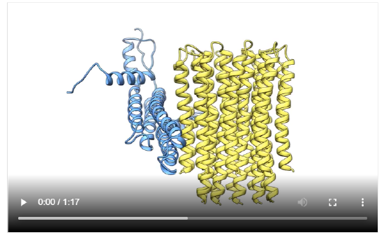
The concerted movement of the c-ring and axle protein with respect to the not physically rotating a3β3 F1 part can be seen in Figure \(\PageIndex{16}\), which is derived from cryoEM structure of different rotated states of bovine ATP synthase.
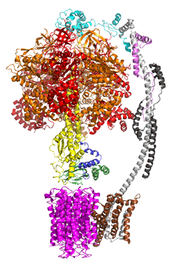
Figure \(\PageIndex{16}\): Structure and conformational states of the bovine mitochondrial ATP synthase (5ARA, 5ARE, 5ARH, 5ARI, 5FIJ, 5FIK, 5FIL)
A phenomena video is available showing the detailed steps in ATP synthesis by ATP synthesis Click on Figure \(\PageIndex{17}\) to get the link to the video.
Figure \(\PageIndex{17}\): ATP synthase in action. Muzzey and Lue, HHMI Institute. For educational and non-commercial use only.
This amazing enzyme can be purified and reconstituted in a lipid vesicle along with bacteriorhodopsin. If these proteins are oriented in the correct fashion, light can cause proton translocation into the lumen of the vesicle creating a transmembrane potential. The proton gradient can collapse as protons move from the lumen through the Fo part of F1Fo ATP synthase, causing ATP synthesis from ADP and Pi in the outside solution. This is shown in Figure \(\PageIndex{18}\).
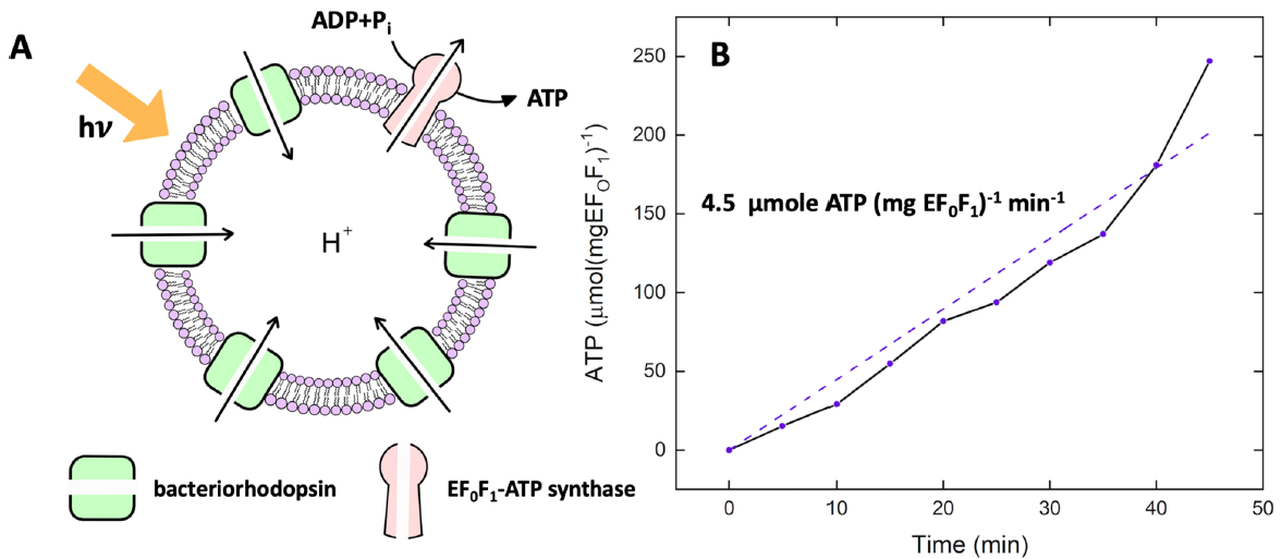
Figure \(\PageIndex{18}\):. Light-driven ATP production. Ahmad et al. ACS Synthetic Biology 2021. https://pubs.acs.org/doi/10.1021/acssynbio.1c00071. https://creativecommons.org/licenses/by/4.0/
Panel(A) shows a cartoon of the light-driven ATP synthesis in lipid vesicles. Panel (B) shows the increase in [ATP] over time.
Proton Gradient Collapse and ATP synthesis - Thermodynamics
Mathematical analyses show that the free energy change on proton gradient collapse can easily power the endergonic synthesis of ATP. Consider a typical pH gradient (-1.4 pH units) across the inner membrane of respiring mitochondria (with the outside having a lower pH than the inside making the inside more depleted in protons). There is a chemical potential difference in protons across the membrane. However, another factor determines the thermodynamic driving force for proton translocation across the membrane. A transmembrane potential exists across the inner membrane of the mitochondria, as it does across most membranes. The source of the membrane potential will be discussed in the signal transduction chapter (Chapter 28). The inside is more negative than the outside, giving the membrane a transmembrane electrical potential. of about -0.14 V. Clearly, protons would be attracted to the other side of the membrane (into the matrix) by this potential difference, which then augments the chemical potential difference as well. A simple mathematical derivation shows that indeed, a proton gradient can supply enough energy for ATP synthesis, especially when coupled to a transmembrane electrical potential. We reshow a small image of the complex and its activities in Figure \(\PageIndex{19}\) to help you through this section

Figure \(\PageIndex{19}\): ATP synthase and its activities. Noji, H., Ueno, H. & Kobayashi, R. Correlation between the numbers of rotation steps in the ATPase and proton-conducting domains of F- and V-ATPases. Biophys Rev 12, 303–307 (2020). https://doi.org/10.1007/s12551-020-00668-7. Creative Commons Attribution 4.0 International License. http://creativecommons.org/licenses/by/4.0/.
Chemical Potential (use G instead of μ)
Since most students use free energy and not chemical potential (which is just free energy /mole at constant T and P, we will derive these equations using free energy G.
Let's consider the free energy of the protons on the outside (low pH, higher concentration) and in the inside (matrix, higher pH, low concentration):
\begin{equation}
\mathrm{H}^{+}{ }_{\text {out }} \longrightarrow \mathrm{H}^{+}{ }_{\text {in }} \mathrm{G}=\mu=\text { chemical potential }(\mathrm{kcal} / \mathrm{mol})
\end{equation}
Now express this as the change in free energy, ΔG
\begin{equation}
\Delta G_{\text {chem }}=G_{\text {in }}-G_{\text {out }}=G^{0}+R T \ln \left[H^{+}\right]_{\text {in }}-\left(G^{0}+R T \ln \left[H^{+}\right]_{\text {out }}\right)
\end{equation}
This can be rewritten as:
\begin{equation}
\Delta G_{\text {ohem }}=\operatorname{RT|n} \frac{\left[H^{+}\right]_{\text {in }}}{\left[H^{+}\right]_{\text {out }}}=2.303 R T\left[-\log \left[H^{+}\right]_{\text {out }}-\left(-\log \left[H^{+}\right]_{\text {in }}\right)\right]
\end{equation}
Hence
\begin{equation}
\Delta \mathrm{G}_{\text {chem }}=2.303 \mathrm{RT}\left(\mathrm{pH}_{\text {out }}-\mathrm{pH}_{\text {in }}\right)=2.303 \mathrm{RT} \Delta \mathrm{pH}
\end{equation}
In respiring mitochondria, ΔpH = -1.4, so
\begin{equation}
\Delta \mathrm{G}{ }_{\text {chem }}=2.303 \mathrm{RT} \Delta \mathrm{pH}=2.303(1.99 \mathrm{cal} / \mathrm{mol} \cdot \mathrm{K})(298 \mathrm{~K})(-1.4)=-1.91 \mathrm{kcal} / \mathrm{mol} \mathrm{} \mathrm{H}^{+}
\end{equation}
Electrical Potential
Consider the relationship between ΔG and the transmembrane electrical potential
\begin{equation}
\Delta G_{\text {elect }}=+Z F \Delta \psi
\end{equation}
where Δψ is the transmembrane potential, Z=+1 (charge on a proton) and F is the Faraday constant
This equation is similar to \begin{equation}
\Delta G \text { elect }=-n F \Delta E
\end{equation}
where ΔE is the cell potential or EMF. If ΔE is + and Δψ is -, then ΔG is -.
In respiring mitochondria, Δψ = -0.140 V (remember that 1 V = 1 J/C). This might seem small but consider this. It is equivalent on a larger scale to an electrical field strength of about 30 million V/meter. Compare this to an electric field right before a lightning strike of about 3,000,000 V/m. Hence
\begin{equation}
\Delta G_{\text {elect }}=+Z F \Delta \Psi=1(96.485 \mathrm{C} / \mathrm{mol})(-0.140 \mathrm{~J} / \mathrm{C}) \times(1 \mathrm{cal} / 4.18 \mathrm{~J})=-3.23 \mathrm{kcal} / \mathrm{mol} \mathrm{H}{ }^{+}
\end{equation}
Electrochemical potential
Now let's add the equations to get the full driving force, the electrochemical potential:
\begin{equation}
\Delta G_{\text {tot }}=2.303 \mathrm{RT} \Delta \mathrm{pH}+\mathrm{ZF} \Delta \psi=-5.15 \mathrm{kcal} / \mathrm{mol} \mathrm{H}{ }^{+}
\end{equation}
This gives
\begin{equation}
\frac{\Delta G_{\text {tot }}}{F}=\frac{2.303 R T \Delta p H++z F \Delta \psi}{F}
\end{equation}
Hence
\begin{equation}
\Delta p=\Delta \psi+\frac{2.303 R T \Delta p H}{F}=\Delta \psi+0.059 \Delta p H=0.224 \mathrm{~V}
\end{equation}
where Δp is the protonmotive force.