

5.2: Techniques to Measure Binding
- Page ID
- 24932


It is often essential to determine the KD for a ML complex since given that number and the concentrations of M and L in the system, we can then predict if M is bound under physiological conditions. Again, this is important since whether M is bound or free will govern its activity. To determine KD, you need to determine ML and L at equilibrium. How can we differentiate free from bound ligand? The following techniques allow such a differentiation.
Techniques that require the separation of bound from the free ligand.
Care must be given to ensure that the equilibrium of M + L ↔ ML is not shifted during the separation technique.
Gel filtration chromatography
Add M to a given concentration of L. Then elute the mixture on a gel filtration column, eluting with the free ligand at the same concentration. The ML complex will elute first and can be quantitated. If you measure the free ligand coming off the column, it will be constant after the ML elutes, with the exception of a single dip near where the free L would elute if the column were eluted without free L in the buffer solution. This dip represents the amount of ligand bound by M.
Membrane filtration
Add M to radiolabelled L, equilibrate, and then filter through a filter that binds M and ML. For instance, a nitrocellulose membrane binds proteins irreversibly. Determine the amount of radiolabeled L on the membrane, which equals [ML].
Precipitation
Add a precipitating agent like ammonium sulfate, which precipitates proteins (both M and ML). Determine the amount of ML.
Techniques that do not require the separation of bound from free ligand.
Equilibrium dialysis
Place M in a dialysis bag and dialyze against a solution containing a ligand whose concentration can be determined using radioisotopic or spectroscopic techniques. At equilibrium, determine free L by sampling the solution surrounding the bag. By mass balance, determine the amount of bound ligand, which for a 1:1 stoichiometry gives ML. Repeat at many different ligand concentrations
Spectroscopy
Find a ligand whose absorbance or fluorescence spectra changes when bound to M. Alternatively, monitor a group on M whose absorbance or fluorescence spectra changes when bound to L.
Isothermal titration calorimetry (ITC)
In ITC, a high-concentration solution of an analyte (ligand) is injected into a cell containing a solution of a binding partner (typically a macromolecule like a protein, nucleic acid, or vesicle). Figure \(\PageIndex{1}\) shows an isothermal titration calorimeter cell,
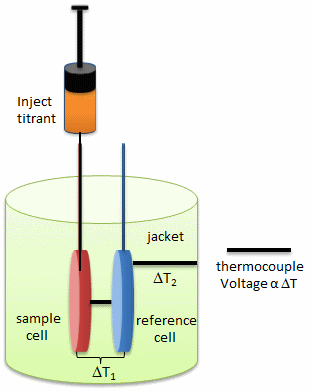
On binding, heat is either released (exothermic reaction) or adsorbed, causing a small temperature change in the sample cell compared to the reference cells containing just a buffer solution. Sensitive thermocouples measure the temperature difference (ΔT1) between the sample and reference cells and apply a current to maintain the difference at a constant value. Multiple injections are made until the macromolecules are saturated with the ligand. The enthalpy change is directly proportional to the amount of ligand bound at each injection, so the observed signal attenuates with time. The actual enthalpy change observed must be corrected for the change in enthalpy on simple dilution of the ligand into buffer solution alone, determined in a separate experiment. The enthalpy changes observed after the macromolecule is saturated with the ligand should be the same as the enthalpy of dilution of the ligand. A binding curve showing enthalpy change as a function of the molar ratio of ligand to binding partner (L0/M0 if L0 >> M0) is then made and mathematically analyzed to determine KD and the stoichiometry of binding. Figure \(\PageIndex{2}\) shows a typical isothermal titration calorimetry data and analysis
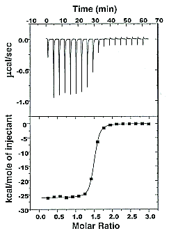
It should be evident in the example above that the binding reaction is exothermic. But why is the graph of ΔH vs the molar ratio of L0/M0 sigmoidal (s-shaped) and not hyperbolic? One clue is that the molar ratio of ligand (titrant) to macromolecule centers around one, so, as explained above, when L0 is not >> M0, the graph might not be hyperbolic. The graphs below show a specific example of a KD and ΔH0 calculated from the titration calorimetry data. We will use them to show why the graph of ΔH vs molar ratio of L0/M0 is sigmoidal.
A specific example illustrates these ideas. A soluble version of the HIV viral membrane protein, gp 120 (4 μM), was placed in the calorimetry cell. A form of its natural ligand, CD4, a membrane receptor protein from T helper cells, was placed in the syringe and titrated into the cell (Myszka et al. 2000). Enthalpy changes/injection were determined. The data was transformed and fit to an equation that shows the ΔH "normalized to the number of moles of ligand injected at each step". Fig."e \(\PageIndex{3}\) shows the raw data (top) and the best-fit model (bottom), assuming a 1:1 stoichiometry of CD4 (the "ligand") to gp 120 (the "macromolecule") and a KD = 190 nM.
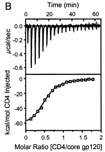
Note that the bottom curve is sigmoidal, not hyperbolic. A single experiment can determine the stoichiometry of binding (n), the KD, and the ΔH0. From the value of ΔHo and KD and the relationship ΔGo = -RTlnKeq = RTlnKD = ΔH0 - TΔS0, the ΔG0 and ΔS0 values can be calculated. No separation of bound from free is required. Enthalpy changes on binding were calculated to be -62 kcal/mol (260 kJ/mol).
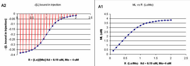
A series of plots can be derived using the standard binding equations (5, 7, and 10 above) to calculate free L and ML at various Lo concentrations and R = L0/M0 ratios. Two were shown earlier to illustrate differences in Y vs L and Y vs L0 when L0 is not >> M0. They are shown again below in Figure \(\PageIndex{4}\).
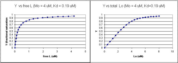
A more precise understanding of the data analyses is shown in Figure \(\PageIndex{5}\), which shows a plot of ML vs R (= [L0]/[M0] (panel A1 right) was made. This curve appears hyperbolic, but it has the same shape as the Y vs L0 graph shown in Figure \(\PageIndex{4}\) (right). However, if the amount of ligand bound at each injection (calculated by subtracting [ML] for injection i+1 from [ML] for injection i) is plotted vs R (= [L0]/[M0]), a sigmoidal curve shown in Figure \(\PageIndex{5}\) (panel A2, left) is seen, which resembles the best-fit graph for the experimentally determine enthalpies in Figure \(\PageIndex{4}\). The relative enthalpy change for each injection is shown in red. Note the graph in Figure \(\PageIndex{5}\) (A2) shows the negative of the amount of ligand bound per injection to make the graph look the that in the graph showing the actual titration calorimetry trace and fit above.
Surface Plasmon Resonance
A newer technique to measure binding is called surface plasmon resonance (SPR), using a sensor chip consisting of a 50 nm layer of gold on a glass surface. A carbohydrate matrix is then added to the gold surface. A macromolecule that contains a binding site for the ligand is covalently attached to the matrix. The binding site on the macromolecule must not be perturbed significantly. A liquid containing the ligand is passed over the binding surface.
The detection system consists of a light beam that passes through a prism on top of the glass layer. The light is reflected, but another component of the wave, called an evanescent wave, passes into the gold layer, where it can excite the Au electrons. If the correct wavelength and angle are chosen, a resonant wave of excited electrons (plasmon resonance) is produced at the gold surface, decreasing the total intensity of the reflected wave. The angle of the SPR is sensitive to the layers attached to the gold, and binding and dissociation of the ligand are sufficient to change the SPR angle, as seen in Figure \(\PageIndex{6}\).
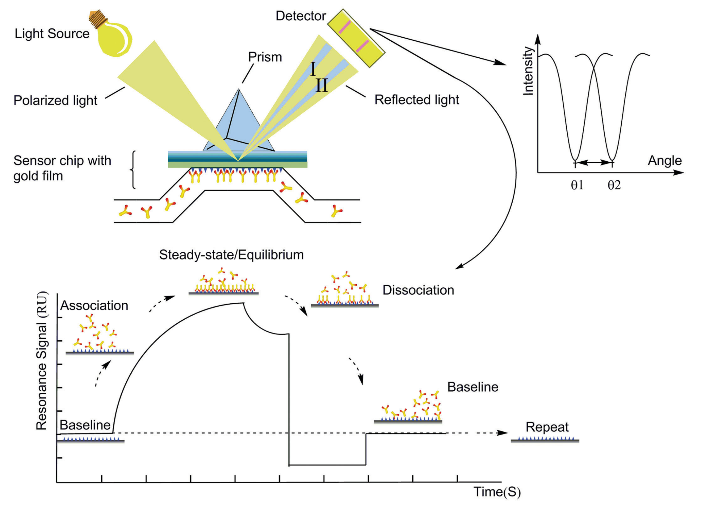
This technique can distinguish fast and slow binding/dissociation of ligands (as reflected in on and off rates) and be used to determine KD values (through measurement of the amount of ligand bond at a given total concentration of ligand or more indirectly through the determination of both kon and koff.
Binding DB: a database of measured binding affinities, focusing chiefly on the interactions of proteiproteinsdered to be drug targets with small, drug-like molecules
PDBBind-CN: a comprehensive collection of the experimentally measured binding affinity data for all biomolecular complexes deposited in the Protein Data Bank (PDB).
Extreme Binding Affinities
An incredibly tight binding interaction has recently been reported for the binding of Cu1+ to the CueR protein from E. Coli. Cu1+ ions are usually kept at very low concentrations in cells to prevent toxicity. Yet some enzymes require Cu. Free copper ions must be present in the cell to allow binding to appropriate sites in proteins. How are these competing concerns regulated in the cell? The total Cu concentration in E. Coli is about 10 μM (10,000 nM), which, given the small size of the bacterium, represents about 10,000 copper ions per cell.
Cells have evolved many mechanisms to control and deliver Cu ions. Copper ions can be delivered to target proteins by copper chaperones (analogs of the chaperone proteins which guide protein folding). CueR in E. Coli appears to regulate the copper-induced expression of genes involved in copper biochemistry (including an enzyme that oxidizes Cu1+ to Cu2+, which is less toxic). One particular gene that is up-regulated is copA. CueR increases the transcription of copA in the presence of Cu, Ag, and Au (coinage metal) ions. Changela et al. developed an in vitro assay to determine the extent of expression of CueR-regulated genes under various ion types and concentrations. In the assay, purified CueR was added to a gene construct containing the promoter (a section of DNA immediately upstream of a gene start site where RNA polymerase binds) for copA. Initially, they found that transcription was always on, even in the presence of a ligand, glutathione, which binds Cu1+ avidly and should keep free Cu1+ levels very low. They switched to an even tighter binding Cu1+ coordinator, cyanide (CN-), to reduce the free Cu1+ levels to even lower levels. Extremely high levels of CN- (millimolar) stopped transcriptional activation, but if additional Cu1+ was added, activation ensued, suggesting that copper binding to the protein was reversible. At 1 mM CN-, transcription increased with the addition of copper ions up to a TOTAL Cu1+ concentration of 60 μm. Under these conditions, the free Cu1+ concentrations were much lower. Given the presence of CN- concentrations used, half-maximal activation occurred at a TOTAL Cu1+ concentration of 0.7 μM. Similar activation was observed by Ag1+ and Au1+, but not by Zn and Hg ions, showing the specificity for monovalent cations over divalent cations.
Knowing the pKa of HCN, stability constants for Cu1+:CN- complexes, and CN- concentrations, Changela et al et al.ced a series of solutions buffered in FREE Cu1+ that extended from 10-18 to 10-23 M (pH 8.0). (For example, the log of the binding constant β, logβ, for the Cu1+ + 2CN- ↔ [Cu(CN)2]- is 21.7. You solved problems involving linked equilibrium if you have taken analytical chemistry.) The free Cu1+ concentration at half-maximal activation of gene reporter transcription, a measure of the dissociation constant, KD, was approximately 1 x 10-21 M (zeptomolar)! Now assume that the volume of the contents of an E. Coli cell is 1.5 x 10⁻¹⁵ L. If there were only one ion of Cu1+ in the cell, it would have a concentration of 10-9 M. The values suggest that there are no free Cu1+ ions in the cell and that only 1 Cu+1 ion in the cell is enough to ensure its binding to CueR and subsequent transcriptional activation of copA.
It is essential for survival that bacterial cells get the correct metal to metalloproteins. A recent review by Waldron and Robinson illustrates how. The cell has many mechanisms for restricting specific binding sites, so metals can get to the right proteins. In addition, the natural order of stability for transition metal complexes must be considered in understanding metal affinities. That stability is given by the Irving-William series shown below (along with Group 2A metal ions). The trend parallels the size of the cation (going from largest to smallest):
Mn2+ < Fe2+ < Co2+ < Ni2+ < Cu2+ > Zn2+ (tightest binding)
- The ability of a protein to change shape on ligand binding allows different metals to bind. For example, cyanobacterium has a high demand for copper and manganese. Manganese might bind to a protein, followed by folding, which traps it in the protein. This unstable metal cannot be replaced by copper, which would ordinarily out-compete Mn2+ for the site.
- Metal transporters help regulate how many ions of each metal are in the cell. Metal sensors are under the control of these metal transporters, regulating gene expression. Once a specific metal has a sufficient concentration for binding, the metal sensors target mRNA to repress specific genes and halt transcription.
- Another enzyme can also be activated for the metal's export. By restricting the concentrations of the competing metals, weaker metal-binding sites remain available.
- Metal sensors can also help to regulate what protein some metals use based on what is available. For example, E. coli switches metabolism to minimize the number of iron-requiring proteins expressed when iron is less abundant.
- Metals are supplied by multiple pathways (in case a specific enzyme is not present) and are trafficked to the correct protein through many ligand-exchange reactions.
- Certain enzymes bind specific metals that cause preferential conformational changes. Hence, if a metal comes along that binds more tightly but is not preferred by the enzyme, it will not trigger the enzyme because it binds in a different manner.
Molecular Basis of High Affinity Interactions
What differentiates high and low affinity binding at the molecular level? Do high affinity interactions have lots of intramolecular H-bonds, salt bridges, van der Waals interactions, or are hydrophobic interactions most important? Recently, the crystal structures of various antibody-protein complexes were determined to study the basis of affinity maturation of antibody molecules. It is well known that antibodies elicited on exposure to a foreign molecule (antigen) are initially of lower affinity than antibodies released later in the immune response. An incredible number of different antibodies can be made by antibody-producing B cells due to genetic mechanisms (combining different variable regions of antibody genes through splicing, imprecise splicing, and hypermutation of critical nucleotides in the genes of antigen binding regions of antibodies). Clones of antibody-producing cells with higher affinity are selected through binding and clonal expansion of these cells. Investigators studied the crystal structure of 4 different antibodies which bind to the same site (epitope) on the protein antigen lysozyme. Increased affinity was correlated with increased buried apolar surface area and not with increased numbers of H bonds or salt bridges. The data for these antibodies are shown below in Table \(\PageIndex{1}\).
| Antibody | H26-HEL | H63-HEL | H10-HEL | H8-HEL |
|---|---|---|---|---|
| KD (nM) | 7.14 | 3.60 | 0.313 | 0.200 |
| Intermolecular Interactions | ||||
| H bonds | 24 | 25 | 20 | 23 |
| VDW contacts | 159 | 144 | 134 | 153 |
| salt bridges | 1 | 1 | 1 | 1 |
| Buried Surface Area | ||||
| ΔASURF (A2) | 1,812 | 1,825 | 1,824 | 1,872 |
| ΔASURF-polar (A2) | 1,149 | 1,101 | 1,075 | 1,052 |
| ΔASURF-apolar (A2) | 663 | 724 | 749 | 820 |
Electrostatic interactions between biological molecules are still very important, even though we may consider them often nonspecific. Consider the binding of DNA binding proteins with positive domains to the negative polyanion, DNA. The initial encounter will be electrostatic in origin and important in targeting the proteins to DNA where other specific interactions may take place.
In a similar example (Yeung, T et al.), it was recently reported that moderately positively charged proteins are directed to endosomes and lysosomes through interactions with negatively charged membrane phosphatidylserine (PS), whereas more positively charged proteins are targeted to the inner surface of the plasma membrane, which is enriched in PS and phosphorylated phosphatidyl inositol derivatives (PIP2, PIP3), as shown in Figure \(\PageIndex{7}\).
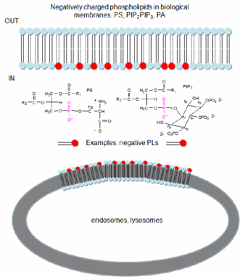
To study this they used the C2 domain of lactadherin (Lact-C2) from milk that binds PS in the presence of calcium. The C2 domain was covalently linked to the green fluorescent protein. This protein contains an internal fluorophore comprised of three amino acids (Ser65-Tyr66-Gly67) that cyclize spontaneously on folding to produce a fluorophore that emits green light. A fusion gene of Lact-C2 and GFP was introduced in wild-type (WT) and mutant yeast lacking PS. It bound to the inner leaflet in WT cells and to endosome and lysosome vesicles but found diffused through the cytoplasm in mutant cells. They also made cationic probes with farnesyl tails that could anchor the soluble probes to membranes. The most positively charged probes were recruited to the plasma membrane inner leaflet, while less charged ones were recruited to internal vesicles. The authors speculate that PS on cytoplasmic membrane layers can target signal transduction proteins to these regions.
Antibodies with Infinite Affinity. Chmura et al. PNAS. 98, pg 8480 (1998)
Docking
The quantitative methods described above do not elucidate the mechanism of binding. Computer programs have been developed that allow the docking of a ligand (small molecule or even another protein) to another protein. The automatic docking of flexible ligands to proteins can be modeled using free programs such as Autodock. Molecular dynamics simulations can also be used to study the actual binding and unbinding processes.
The Crowded Cell
Most binding studies are performed in vitro with dilution concentrations of both macromolecule and ligand. Are these conditions illustrious of conditions inside a cell? The answer is no! Cells are crowded with organelles, macromolecular complexes, and cytoskeletal components that provide an internal architecture to the cell. Total macromolecule concentration in the cell has been estimated to be as high as 400 g/1L = 400 g/1000 mL = 0.4 g/mL = 400 mg/mL. Try to dissolve a water-soluble protein like albumin at those concentrations! From 5 to 40% of the entire cellular volume is occupied with large molecules, and at the upper range, very little space exists for other large macromolecules. A representation showing the crowdedness of a bacterial cell at the atom level is shown in Figure \(\PageIndex{8}\).
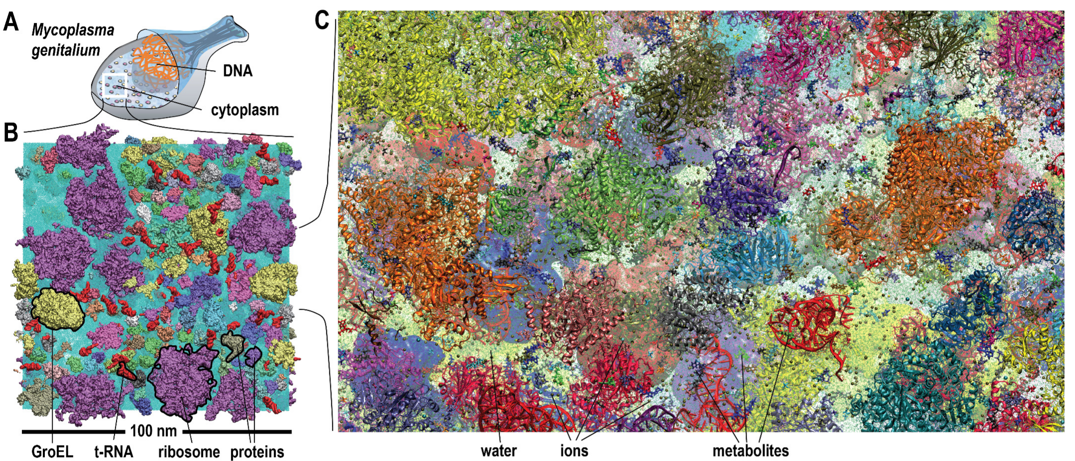
Imagine trying to diffuse through that!